Rating:
Information pump assy, supply Denso
Product
Fuel Injection Pump
Vehicle engine
INDUSTRIAL A68TI
Engine
A68TI
Serial start-end
0802-
Info
Injector Nozzle
KUBOTA
PUMP ASSY, SUPPLY
MA
- #..NEW PARTS ARE INTERCHANGEABLE WITH OLD ONE,
- IF NO.3,4 ARE CHANGED AT THE SAME TIME.
Compare Prices: .
As an associate, we earn commssions on qualifying purchases through the links below

$542.99
07 Apr 2025
CN: TUF Parts
Fuel Injection Pump 294000-0840 2940000840 A68TI Compatible with Kubota 1G41050502
KoovDem Part Number:104135-4032 1041354032 || Part Name: Fuel Injection Pump || Compatible with New Holland 3415, TC35DA, TC40DA, TC48DA, and TC55DA tractors, as well as L160, C175, and L170 machinery. || This product is specifically engineered to integrate smoothly with a range of Perkins Engine models, including 404D, 404D-22, 404D-22T, 404D-22TA, 404C-22, and 404C-22T. It guarantees top-notch performance and functionality. Whether you are looking to enhance or repair parts, this product serves as a dependable and effective option for your equipment.
KoovDem Part Number:104135-4032 1041354032 || Part Name: Fuel Injection Pump || Compatible with New Holland 3415, TC35DA, TC40DA, TC48DA, and TC55DA tractors, as well as L160, C175, and L170 machinery. || This product is specifically engineered to integrate smoothly with a range of Perkins Engine models, including 404D, 404D-22, 404D-22T, 404D-22TA, 404C-22, and 404C-22T. It guarantees top-notch performance and functionality. Whether you are looking to enhance or repair parts, this product serves as a dependable and effective option for your equipment.

$866.75
06 Mar 2025
0.1102[0.05] pounds
CN: jiaxuan1227
Diesel Fuel Injector Injection Pump 294000-0840 1G410-50501
HXYAIEOGD Ensure the continuous and stable operation of the engine. || The installation procedure is simple. || Ensure OE number before placing order. || The warranty period is 12 months. || 1 piece jet pump
HXYAIEOGD Ensure the continuous and stable operation of the engine. || The installation procedure is simple. || Ensure OE number before placing order. || The warranty period is 12 months. || 1 piece jet pump

$1,064.55
06 Mar 2025
0.1102[0.05] pounds
CN: zhuxiu848 mall
High Pressure Common Rail Fuel Diesel Injection Pump 294000-0840 1G410-50501 Compatible for Kubota A68T1
FEMKFAXF The Fuel Pump helps your car run smoothly and efficiently. || Our pumps have undergone rigorous tests to evaluate their performance and quality standards. || High Pressure Common Rail Fuel Diesel Injection Pump 294000-0840 1G410-50501 Compatible for Kubota A68T1 || The fuel injection pump aims to provide an accurate amount of fuel for each engine cylinder to ensure the best combustion and maximum power output. || Thoroughly remanufactured - this fuel injector pump has been completely disassembled, cleaned, inspected, reassembled with new internal components and tested to be leak.
FEMKFAXF The Fuel Pump helps your car run smoothly and efficiently. || Our pumps have undergone rigorous tests to evaluate their performance and quality standards. || High Pressure Common Rail Fuel Diesel Injection Pump 294000-0840 1G410-50501 Compatible for Kubota A68T1 || The fuel injection pump aims to provide an accurate amount of fuel for each engine cylinder to ensure the best combustion and maximum power output. || Thoroughly remanufactured - this fuel injector pump has been completely disassembled, cleaned, inspected, reassembled with new internal components and tested to be leak.
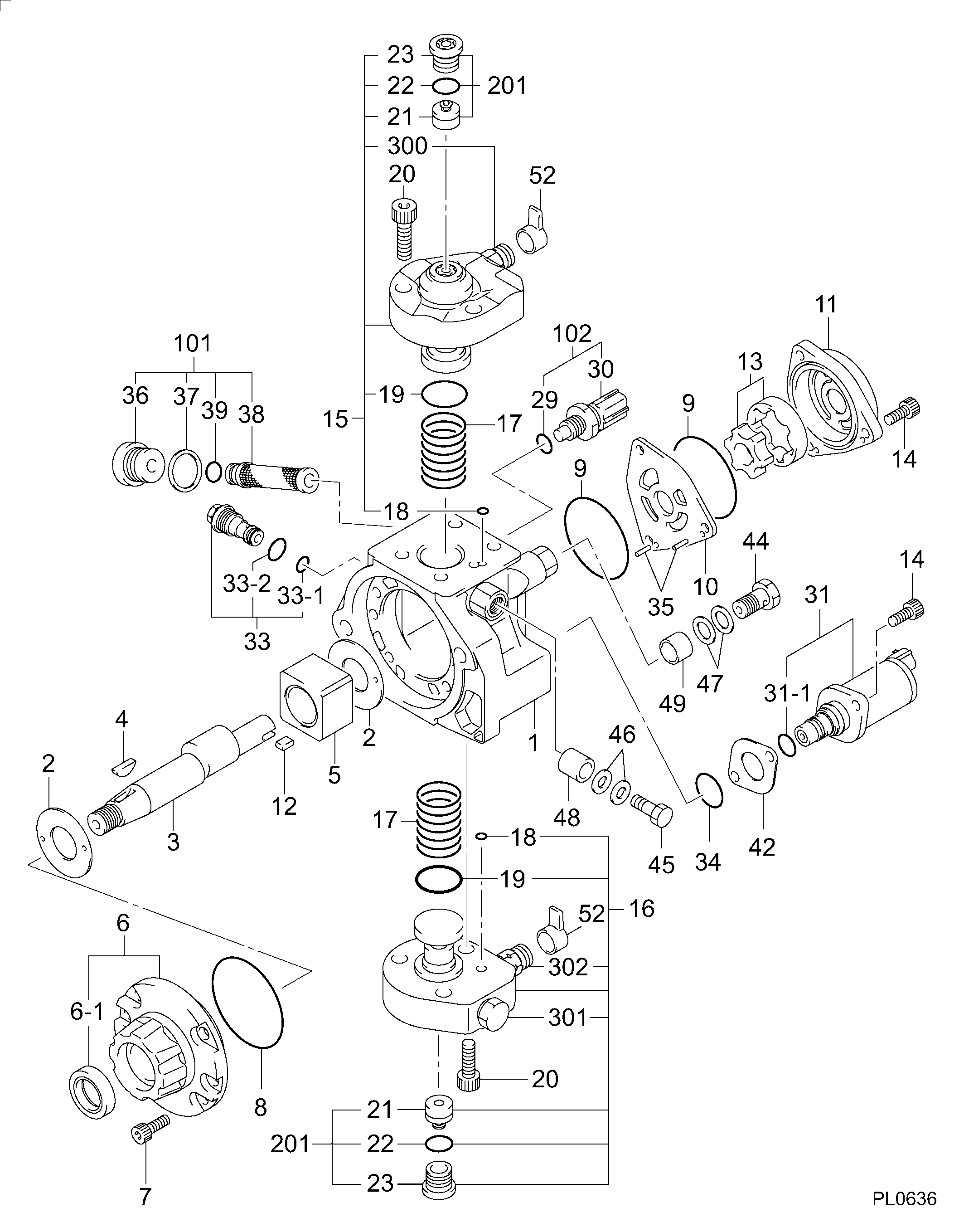
Components :
Scheme #.#:
№
Qty
Part num
Name
Remarks
Manufacture num
000
[01]
29400-00840
PUMP ASSY, SUPPLY
HP3
1G410-50501
KUBOTA
Include in ##:
29400-00840
as PUMP ASSY, SUPPLY
Cross reference number
Part num
Firm num
Firm
Name
29400-00840
1G410-5050
KUBOTA
PUMP ASSY, SUPPLY
2940000840
1G410-50501
KUBOTA
PUMP ASSY SUPPLY
2940000840
1G410-50501
KUBOTA
PUMP ASSY, SUPPLY
2940000840
1G410-50502
KUBOTA
PUMP ASSY, SUPPLY
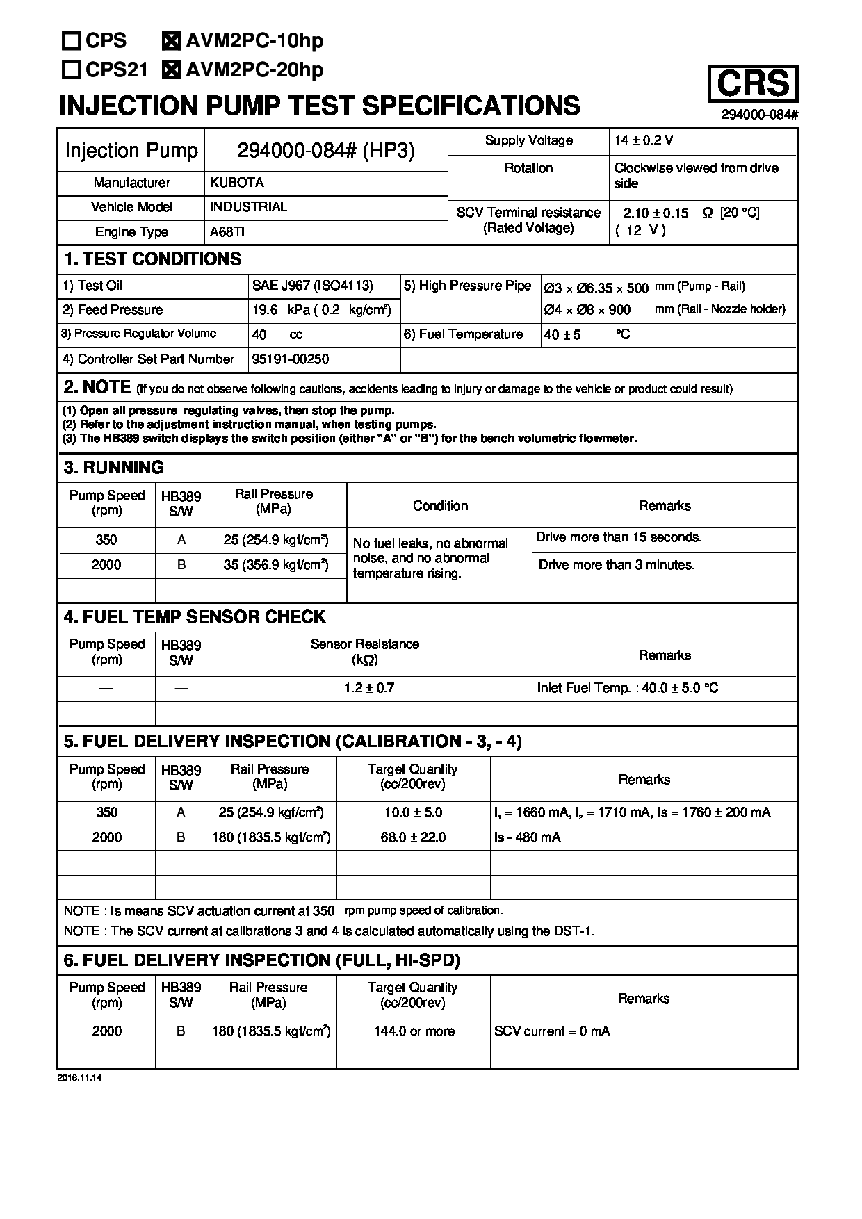
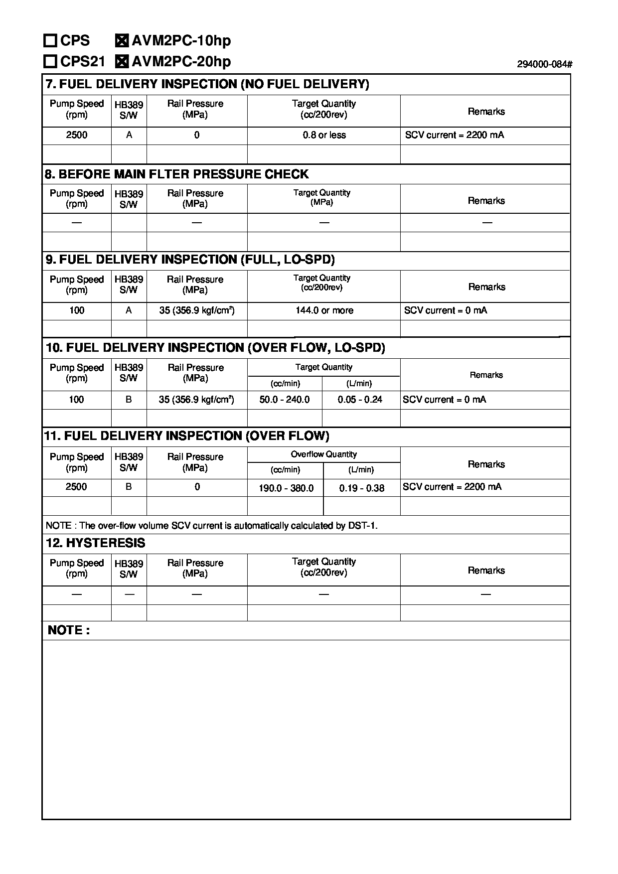
Test Calibration Data:
02EN084000
1G410-50501
02EN084000
1G410-50501
02EN084000
1G410-50501
Information:
WATER SLEEVE CLAMP
1. Clamp.3. Use water sleeve tool (2) to move water sleeve (3) into front cover.4. Remove the cylinder head retaining bolts (4) and (5).
MOVING WATER SLEEVE
2. 8S6692 Water Sleeve Tool. 3. Water sleeve.
CYLINDER HEAD
4. Bolts (four each head). 5. Bolts (eighteen each head).
Be sure fuel injection nozzles are removed before removing head. Nozzles extend through the head and nozzle tips can be broken off if nozzles are not removed from the head.
5. Install two 1P7407 Lifting Eye Bolts in the cylinder head. Attach a hoist and remove the cylinder head assembly, the weight is approx. 85 lbs. (39 kg).
REMOVING CYLINDER HEADInstall Cylinder Head Assemblies
1. Clean the mating surfaces of the cylinder head and cylinder block. Install new cylinder head gasket, clean and dry. Clean bores in cylinder head and inspect and lubricate O-rings for water sleeves.2. Install two 1P7407 Lifting Eye Bolts in the cylinder head. Attach a hoist and install the cylinder head assembly. Coat the cylinder head retaining bolt threads with 9M3710 Anti-Seize Compound. Install the bolts and tighten in the following Step sequence. Step A: Tighten bolts 1 through 18 in numerical order to 60 10 lb. ft. (8.3 1.4 mkg).Step B: Retighten bolts 1 through 18 in numerical order to 95 5 lb. ft. (13.1 0.7 mkg).Step C: Finally tighten bolts 1 through 18 in numerical order (hand tighten only) to 95 5 lb. ft. (13.1 0.7 mkg).Step D: Tighten bolts 19, 20, 21, and 22 in numerical order to 32 5 lb. ft. (4.4 0.7 mkg).
CYLINDER HEAD BOLT LOCATION3. Use the 8S6692 Water Sleeve Tool to slide water sleeve into cylinder head and install clamp.Disassemble Cylinder Head
1. Place head on the FT806 Cylinder Head Bench or the 8S6691 Cylinder Head Stand. Use FT967 Adapter Plates to mount head on the FT806 Cylinder Head Bench.2. Use a 5S1330 or 7F4291 Valve Spring Compressor (1) to remove the valves and valve springs.
REMOVING VALVES
1. 5S1330 Valve Spring Compressor illustrated.3. Use the 8S2263 Valve Spring Tester to check valve spring tension.4. The exhaust valve seats have replaceable inserts. To remove, use the 8S7170 Valve Seat Insert Puller Group.
REMOVING EXHAUST VALVE SEAT INSERTS The valve guides are cast in the cylinder head. If the guides show wear or bellmouthing, they can be restored to original tolerances through knurling.Assemble Cylinder Head
1. Lubricate valve stems with clean engine oil (SAE 30) before installing valves into cylinder head. Earlier engines use a valve spring retainer and washer combination instead of the one piece valve spring retainer shown.
CYLINDER HEAD