Rating:
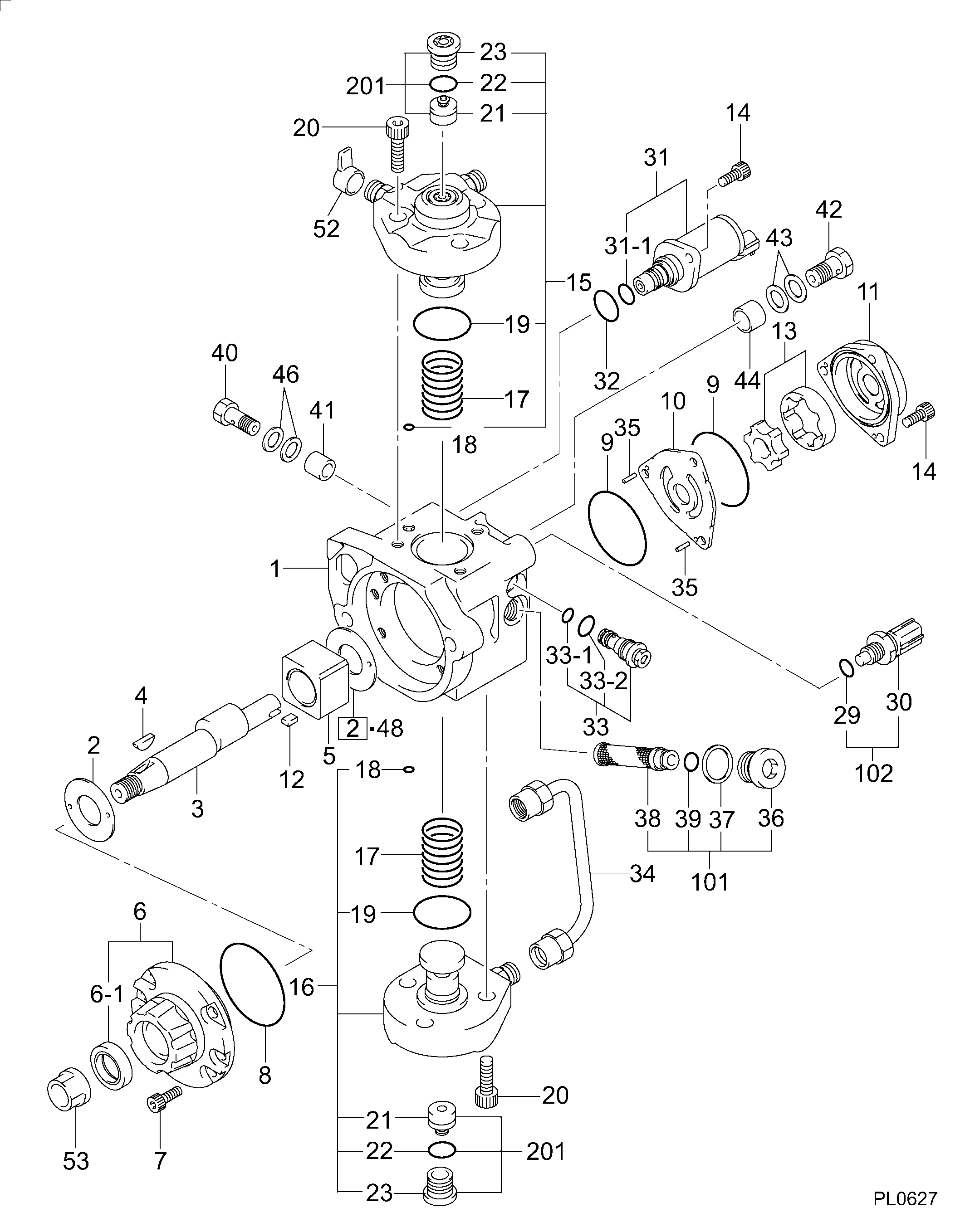
Information pump assy, supply Denso
Compare Prices: .
As an associate, we earn commssions on qualifying purchases through the links below

Fuel Injection Pump Type 294000-0730 33100-48000 Well-suited for Hyundai Diesel Engine D4GA
Podafu Part Name: Fuel Injection Pump || Part Number: 294000-0730 || Applicable: Compatible with Hyundai Diesel Engine D4GA || The fuel injection pump has a long service life, low maintenance frequency, and high reliability || Before purchasing, please carefully check if the product is suitable for your vehicle by reviewing the part number and photos.
Podafu Part Name: Fuel Injection Pump || Part Number: 294000-0730 || Applicable: Compatible with Hyundai Diesel Engine D4GA || The fuel injection pump has a long service life, low maintenance frequency, and high reliability || Before purchasing, please carefully check if the product is suitable for your vehicle by reviewing the part number and photos.

Fuel Injection Pump 294000-0730 33100-48000 for Hyundai Engine D4GA
100% Apollo part number:294000-0730 33100-48000 || application: for Hyundai Engine D4GA
100% Apollo part number:294000-0730 33100-48000 || application: for Hyundai Engine D4GA

Fits for Hyundai Diesel Engine D4GA Hconcet Fuel Injection Pump 33100-48000 294000-0730
KoovDem Part Name: Fuel Injection Pump || Diesel Engine Model: D4GA || Suitable for use with the Hyundai Diesel Engine D4GA. || Upgrade your vehicle's performance with the Fuel Injection Pump (part numbers 33100-48000 and 294000-0730). Designed to deliver fuel at the right pressure and volume for proper combustion, this high-quality and reliable component ensures optimal efficiency and smooth engine operation. Replace your old or faulty pump to maintain the functionality of your fuel system. Order now for enhanced performance and efficiency.
KoovDem Part Name: Fuel Injection Pump || Diesel Engine Model: D4GA || Suitable for use with the Hyundai Diesel Engine D4GA. || Upgrade your vehicle's performance with the Fuel Injection Pump (part numbers 33100-48000 and 294000-0730). Designed to deliver fuel at the right pressure and volume for proper combustion, this high-quality and reliable component ensures optimal efficiency and smooth engine operation. Replace your old or faulty pump to maintain the functionality of your fuel system. Order now for enhanced performance and efficiency.
Components :
Scheme #.#:
№
Qty
Part num
Name
Remarks
Manufacture num
000
[01]
29400-00732
PUMP ASSY, SUPPLY
3310048000
HYN
Include in ##:
29400-00732
as PUMP ASSY, SUPPLY
Cross reference number
Part num
Firm num
Firm
Name
29400-00732
3310048000
PUMP ASSY, SUPPLY
Information:
EXHAUST MANIFOLD
1. Locks (four each side). 2. Retaining bolts (eight each side). 3. Exhaust manifold (one each side).Install Exhaust Manifold
1. Clean the exhaust manifold gasket mounting surfaces.2. Position the gasket and exhaust manifold on the engine and install the retaining bolts with locks. Tighten retaining bolts to 32 5 lb. ft. (4.4 0.7 mkg). Bend tabs on locks over flats of retaining bolt heads. Lock tabs must be bent over flats of retaining bolt heads. If necessary to align flats, tighten bolts a maximum additional turn of 30°. Do not loosen bolts to align flats.Disassemble Crankcase Ventilation Valve
1. Remove screws (2) that hold cover (3) on housing (1).
VENTILATION VALVE
1. Housing. 2. Screws (seven). 3. Cover.2. Remove cover (3) and spring (4).
REMOVING COVER
1. Housing. 3. Cover. 4. Spring.3. Remove the piston, sleeve (8), retainer (9), and diaphragm (7) from housing (1) as a unit. Remove inner sleeve (6) and gasket (5) from housing (1).
DISASSEMBLING VALVE
1. Housing. 5. Gasket. 6. Inner sleeve. 7. Diaphragm. 8. Sleeve. 9. Retainer.4. Remove nut (12), washer (13), spacer (11), piston (10), diaphragm (7), and the retainer from sleeve (8).
REMOVING DIAPHRAGM
7. Diaphragm. 8. Sleeve. 10. Piston. 11. Spacer. 12. Nut. 13. Washer.Assemble Crankcase Ventilation Valve
1. Put 5H2471 Gasket Cement on both sides of gasket (5) and install the gasket on housing (1). Install inner sleeve (6) in housing (1).2. Inspect diaphragm (7) for damage. Put piston (10) against side of diaphragm (7) that is stamped "piston side" and put retainer (9) in diaphragm (7).
INSTALLING INNER SLEEVE
1. Housing. 5. Gasket. 6. Inner sleeve.
ASSEMBLING DIAPHRAGM
7. Diaphragm. 9. Retainer. 10. Piston.3. Put the screw through sleeve (8), retainer (9), diaphragm (7), and piston (10). Put spacer (11), washer (13), and nut (12) on the screw and tighten the nut.
ASSEMBLING DIAPHRAGM
7. Diaphragm. 8. Sleeve. 10. Piston. 11. Spacer. 12. Nut. 13. Washer.4. Put 5H2471 Gasket Cement on both sides of the diaphragm (7) to prevent it from distorting and tearing during assembly. Install the assembled diaphragm unit in the inner sleeve (6) and housing (1).
INSTALLING DIAPHRAGM
1. Housing. 5. Gasket. 6. Inner sleeve. 7. Diaphragm. 8. Sleeve. 9. Retainer.5. With the diaphragm unit installed, put spring (4) on the spacer and install cover (3) being sure spring (4) goes over plug (14).
INSTALLING COVER
1. Housing. 3. Cover. 4. Spring. 14. Plug.6. Put screws (2) in housing (1) and tighten the screws.
COVER INSTALLED
1. Housing. 2. Screws (seven). 3. Cover.