Rating:
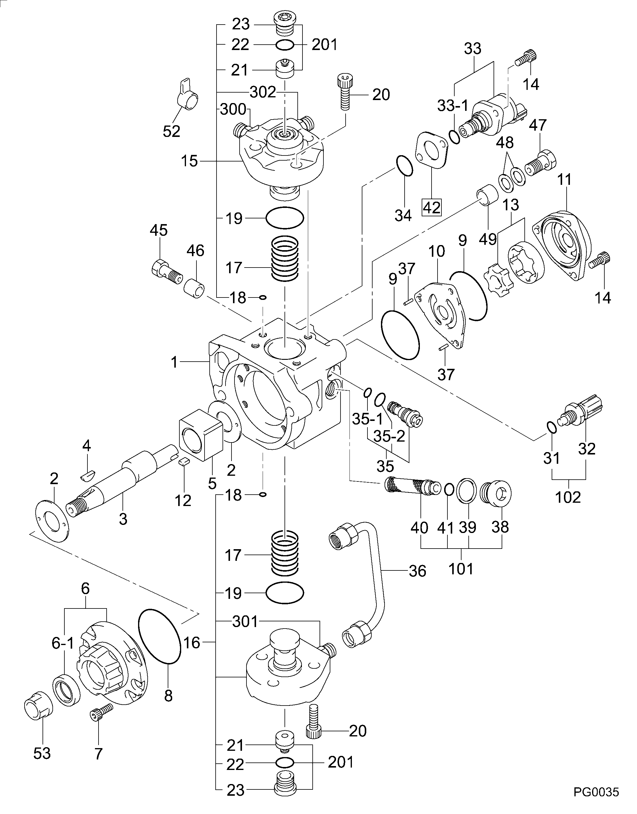
Information pump assy, supply Denso
Compare Prices: .
As an associate, we earn commssions on qualifying purchases through the links below

Fuel Injection Pump 294000-0610 22100-E0035 22100-E0030 294000-0611 HP3 Fuel Pump Assembly,Compatible For Denso
DYVWMRKX Performance optimization: Optimize fuel supply efficiency, reduce engine vibration, and improve smooth power output. || Perfect matching, easily solving the problem of fuel pump replacement and adaptation, ensuring seamless integration with electrical equipment. || Adopting precision machining technology to ensure stable fuel injection pressure, improve engine combustion efficiency, and reduce fuel consumption. || Accurately control the fuel injection quantity and injection pressure, provide stable and efficient fuel to the engine, optimize fuel combustion efficiency, improve engine power output, and reduce fuel consumption. || Fuel Injection Pump 294000-0610, High Pressure Oil Pump 22100-E0035, Fuel Injection Pump, HP3 High Pressure Oil Pump Assy, 22100-E0030 Fuel Pump, 294000-0611 Diesel Pump, High Pressure Fuel Pump Replacement, Fuel Pump Repair Parts
DYVWMRKX Performance optimization: Optimize fuel supply efficiency, reduce engine vibration, and improve smooth power output. || Perfect matching, easily solving the problem of fuel pump replacement and adaptation, ensuring seamless integration with electrical equipment. || Adopting precision machining technology to ensure stable fuel injection pressure, improve engine combustion efficiency, and reduce fuel consumption. || Accurately control the fuel injection quantity and injection pressure, provide stable and efficient fuel to the engine, optimize fuel combustion efficiency, improve engine power output, and reduce fuel consumption. || Fuel Injection Pump 294000-0610, High Pressure Oil Pump 22100-E0035, Fuel Injection Pump, HP3 High Pressure Oil Pump Assy, 22100-E0030 Fuel Pump, 294000-0611 Diesel Pump, High Pressure Fuel Pump Replacement, Fuel Pump Repair Parts

Fuel Injection Pump, Compatible With Denso Fuel Pump Assembly 294000-0611 294000-0610 22100-E0030 22100-E0035
CHENUXO Fuel Injection Pump , Compatible With Denso Fuel Pump Assembly 294000-0611 294000-0610 22100-E0030 22100-E0035 || Filtering impurities: It can effectively filter impurities in fuel and maintain engine and fuel system components. || Quick response: It has the ability to start and respond quickly, and can quickly establish stable fuel pressure. || Efficient and energy-saving: It can meet the fuel demand of the engine while reducing energy consumption, which helps to improve fuel economy. || High reliability: Adopting advanced manufacturing processes to effectively reduce wear and tear. Ensure stable operation in various harsh environments.
CHENUXO Fuel Injection Pump , Compatible With Denso Fuel Pump Assembly 294000-0611 294000-0610 22100-E0030 22100-E0035 || Filtering impurities: It can effectively filter impurities in fuel and maintain engine and fuel system components. || Quick response: It has the ability to start and respond quickly, and can quickly establish stable fuel pressure. || Efficient and energy-saving: It can meet the fuel demand of the engine while reducing energy consumption, which helps to improve fuel economy. || High reliability: Adopting advanced manufacturing processes to effectively reduce wear and tear. Ensure stable operation in various harsh environments.

Fuel Pump 294000-0611 Engine Oil Pump
DFGUFG [OE NO. & Part NO] 294000-0611 || [Product Name and Model] Fuel Injection Pump || [Easy Installation] Standardized interface design, no additional modification required, simple and quick installation process, users can easily complete replacement and maintenance. || [Quality Assurance] Products undergo rigorous quality testing to ensure reliable performance and high-quality after-sales service, so you have no worries. || [Reliable Performance] Provides excellent fuel injection performance, optimizes engine operating efficiency, and helps equipment operate stably for a long time.
DFGUFG [OE NO. & Part NO] 294000-0611 || [Product Name and Model] Fuel Injection Pump || [Easy Installation] Standardized interface design, no additional modification required, simple and quick installation process, users can easily complete replacement and maintenance. || [Quality Assurance] Products undergo rigorous quality testing to ensure reliable performance and high-quality after-sales service, so you have no worries. || [Reliable Performance] Provides excellent fuel injection performance, optimizes engine operating efficiency, and helps equipment operate stably for a long time.
Include in ##:
Cross reference number
Part num
Firm num
Firm
Name
29400-00611
22100-E003
PUMP ASSY, SUPPLY
Information:
start by:remove turbocharger 1. Install turbocharger in tool group (A). Put marks on th three housings of the turbocharger for correct installation and alignment at assembly. Remove "V" clamp (2) and compressor housing (1). 2. Remove "V" clamp (3). Remove the cartridge housing (5) from the turbine housing (4). 3. Install tool (C) in tool (B) and put the cartridge assembly in tool (C) as shown. Use tool (D) to remove the nut that holds compressor wheel (6).
When the nut is loosened, do not put a side force on the shaft.
The oil used to heat the compressor wheel must have a flash point (the temperature at which the oil will burn) above 400°F (204°C).
4. Install tool (H) on tool (E). Heat tool (E) to a temperature of 350°F (177°C). Install the cartridge assembly on tool (H) so that only the compressor wheel is in the oil. Heat the compressor wheel for no more than 10 minutes.
Do not let the turbine wheel hit the bottom of the press.
5. Install tool (H) on tool (G). Put the cartridge assembly in tool (H) as shown. Remove compressor wheel (6) with an arbor press and tool (F). Step 5 must be done before the compressor wheel becomes cooler. 6. Put the turbine wheel in tool (C). Remove seal ring (8) and shroud (7) from the shaft. 7. Bend the tabs of the locks from bolts (10) and remove the bolts and locks.8. Remove backplate assembly (11) from the cartridge housing. Remove spacer (9) from backplate assembly (11). Remove the seal rings from spacer (9).9. Remove the collar from behind backplate assembly (11). 10. Remove thrust bearing (13) and O-ring seal (12) from the cartridge housing. 11. Remove top bearing (14) and the washer from the cartridge housing. Put a long dye mark on the top face of bearing (14). 12. Use tool (J) and remove the two rings that hold top and bottom bearings in position. Remove the bottom bearing and washer. Put a short dye mark on the bearing. The dye marks are used for identification of the bearings when they are installed.13. Use tool (J) and remove the last ring that holds the bottom bearing in position from the cartridge housing.14. Check all the parts of the turbocharger for damage. If the parts have damage, use new parts for replacement. See SPECIAL INSTRUCTION FORM NO. SMHS6854 for TURBOCHARGER RECONDITIONING. Also see GUIDELINE FOR REUSABLE PARTS FORM NO. SEBF8018.Assemble Turbocharger (Airesearch TV81)
1. Make sure that all of the oil passages in the turbocharger cartridge housing are clean and free of dirt and foreign material.2. Put clean engine oil on all parts of the cartridge assembly.
Rings (1), (4) and (5) must be installed with the round edge of the rings toward the bearings.
3. Install ring (4) in the