Rating:
Information pump assy, supply Denso
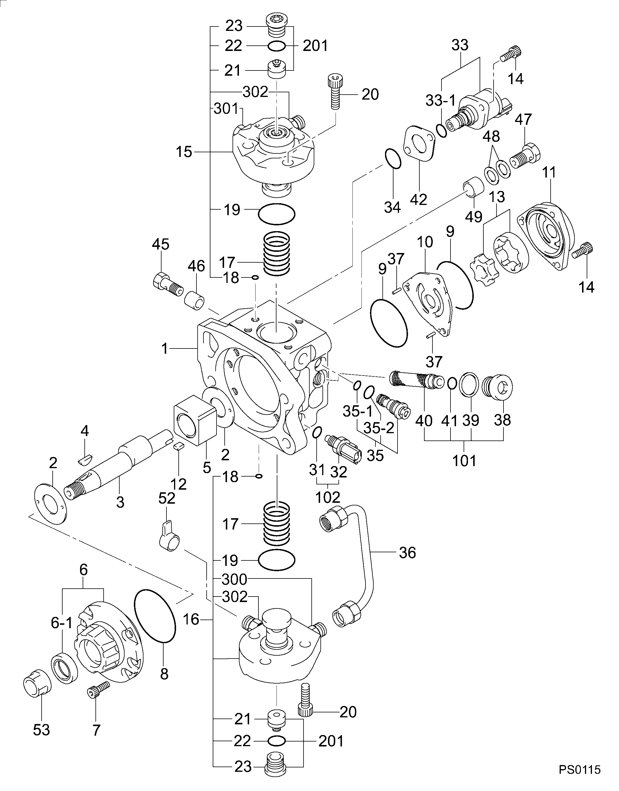
Product
Fuel Injection Pump
Vehicle engine
DUTRO N04C-TR
Engine
N04C-TR
Serial start-end
0610-
Info
Injector Nozzle
Product
Fuel Injection Pump
Vehicle engine
DUTRO N04C-TS
Engine
N04C-TS
Serial start-end
0610-
Info
Injector Nozzle
Product
Fuel Injection Pump
Vehicle engine
DUTRO N04C-TT
Engine
N04C-TT
Serial start-end
0610-
Info
Injector Nozzle
Product
Fuel Injection Pump
Vehicle engine
DUTRO N04C-TU
Engine
N04C-TU
Serial start-end
0610-
Info
Injector Nozzle
Product
Fuel Injection Pump
Vehicle engine
DUTRO N04C-TV
Engine
N04C-TV
Serial start-end
0610-
Info
Injector Nozzle
TOYOTA
PUMP ASSY, SUPPLY
AA
- #..NEW PARTS ARE INTERCHANGEABLE WITH OLD ONE,
- IF NO.3,4 ARE CHANGED AT THE SAME TIME.
HINO
PUMP ASSY, SUPPLY
DA
- *1 REFER TO SERVICE BULLETIN DOCID 00400687E.
- (VIA THE "REPAIR INFO " MENU)
- #..NEW PARTS ARE INTERCHANGEABLE WITH OLD ONE,
- IF NO.3,4 ARE CHANGED AT THE SAME TIME.
Compare Prices: .
As an associate, we earn commssions on qualifying purchases through the links below

Fuel Injection Pump 294000-0590 22100-E0060 for Hino Engine N04C Truck 300 Series
ADPelcote Part number:294000-0590 || Applications:for Hino Engine N04C Truck 300 Series
ADPelcote Part number:294000-0590 || Applications:for Hino Engine N04C Truck 300 Series

HP3 Common Rail Fuel Injection Pump 294000-0590 294000-0591 22100-E0060 22100-E0061 Compatible With HINO N04C
HXYAIEOGD Ensure the continuous and stable operation of the engine. || The installation procedure is simple. || Ensure OE number before placing order. || The warranty period is 12 months. || 1 piece jet pump
HXYAIEOGD Ensure the continuous and stable operation of the engine. || The installation procedure is simple. || Ensure OE number before placing order. || The warranty period is 12 months. || 1 piece jet pump

HP3 Common Rail Fuel Pump 294000-0590 294000-0591 294000-1950 294000-1592 22100-E0060 Compatible With HINO N04C
HXYAIEOGD Ensure the continuous and stable operation of the engine. || The installation procedure is simple. || Ensure OE number before placing order. || The warranty period is 12 months. || 1 piece jet pump
HXYAIEOGD Ensure the continuous and stable operation of the engine. || The installation procedure is simple. || Ensure OE number before placing order. || The warranty period is 12 months. || 1 piece jet pump
You can buy:

Include in ##:
Cross reference number
Part num
Firm num
Firm
Name
29400-00590
22100-E006
TOYOTA
PUMP ASSY, SUPPLY
2940000590
22100-E0060
HINO
PUMP ASSY SUPPLY
2940000590
22100-E0060
HINO
PUMP ASSY, SUPPLY
2940000590
22100-E0061
HINO
PUMP ASSY SUPPLY
2940000590
22100-E0061
HINO
PUMP ASSY, SUPPLY
2940000590
22100-E0062
HINO
PUMP ASSY SUPPLY
2940000590
22100-E0062
HINO
PUMP ASSY, SUPPLY
2940000590
22100-E0063
HINO
PUMP ASSY, SUPPLY
2940000590
22100-E0064
HINO
PUMP ASSY, SUPPLY
2940000590
22100-E0065
HINO
PUMP ASSY, SUPPLY
2940000590
22100-E0066
HINO
PUMP ASSY, SUPPLY
2940000590
22100-E0067
HINO
PUMP ASSY, SUPPLY
2940000590
22100-78230
TOYOTA
PUMP ASSY SUPPLY
2940000590
22100-78231
TOYOTA
PUMP ASSY, SUPPLY
2940000590
22100-78232
TOYOTA
PUMP ASSY, SUPPLY
2940000590
22100-78233
TOYOTA
PUMP ASSY, SUPPLY
2940000590
22100-78234
TOYOTA
PUMP ASSY, SUPPLY
2940000590
22100-78235
TOYOTA
PUMP ASSY, SUPPLY
2940000590
22100-78236
TOYOTA
PUMP ASSY, SUPPLY
2940000590
22100-78237
TOYOTA
PUMP ASSY, SUPPLY
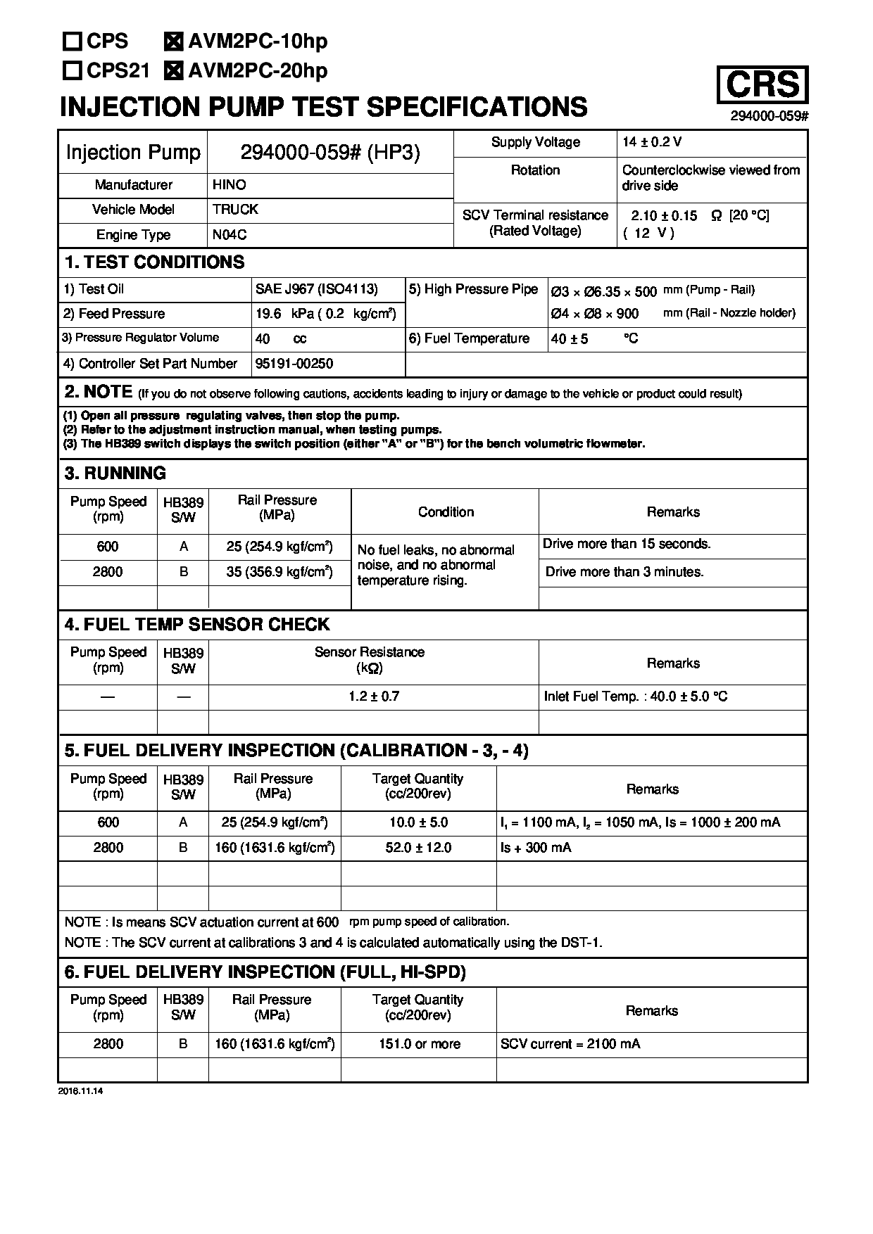
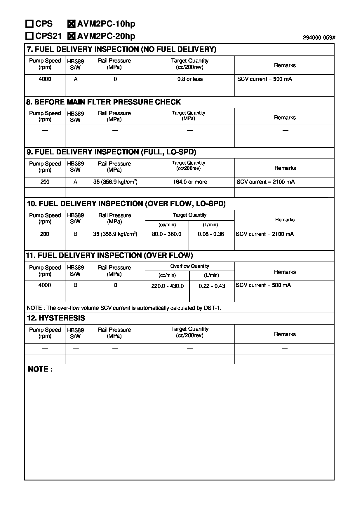
Test Calibration Data:
02EN059000
22100-E0060
02EN059000
22100-E0060
02EN059000
22100-E0060
02EN059000
22100-E0060
02EN059000
22100-E0060
02EN059000
22100-E0060
02EN059000
22100-E0060
02EN059000
22100-E0060
02EN059000
22100-E0060
02EN059000
22100-E0060
Information:
start by: a) remove oil pump1. Check the connecting rods and caps for their identification and location.2. Turn crankshaft until connecting rod caps are in position shown. 3. Remove the nuts (1) and the cap from connecting rod. Remove lower half of bearing from cap.4. Push the connecting rod away from the crankshaft. Remove the upper half of bearing from connecting rod. Install the bearings dry when the clearance checks are made. Put clean engine oil on the bearings for final assembly.5. Install upper half of bearing in connecting rod.6. Pull the connecting rod slowly on to the crankshaft.7. Install lower half of bearing in cap. Be sure the tabs in back of bearings are in the tab grooves of connecting rod and cap.
Do not use an impact wrench to tighten the bolts the additional 120° 5°.
8. Use Plastigage (A) to check bearing clearance.9. Put Plastigage (A) on the bearing.10. Put clean engine oil on threads of rod bolts and seat surfaces of nuts. Be sure the cylinder numbers on the rod cap and rod are the same and are on the same side of the connecting rod. Numbers are on the same side of rod and caps as are the grooves for the bearing tabs. If new rods are installed, put the cylinder number on the rod and cap. Do not turn the crankshaft when Plastigage (A) is in position. 11. Install the rod caps (2). Install the nuts. Tighten each nut to a torque of 60 6 lb. ft. (80 8 N m). Put a mark on the nuts and cap and tighten nuts an extra 120° 5° from the mark. Remove the rod cap. Remove Plastigage (A) and check the bearing clearance. The bearing clearance must be .0028 to .0066 in. (0.071 to 0.168 mm) for new bearings. Maximum clearance with used bearings is .010 in. (0.25 mm).12. Put clean engine oil on lower half of bearing. Install rod cap again. Tighten each nut to 60 6 lb.ft. (80 8 N m). Put a mark on nuts and cap and tighten nuts an extra 120° 5° from mark.13. Do Steps 1 through 12 for remainder of connecting rod bearings.end by:a) install oil pump