Rating:
Information pump assy, supply Denso
Compare Prices: .
As an associate, we earn commssions on qualifying purchases through the links below

Fuel Pump 294000-0294 33100-45700 for Hyundai Mighty County HD78 Engine
oiasdfhjdg Product name:Fuel Pump || Part Number:294000-0294 33100-45700 || APPlication:for Hyundai Mighty County HD78 Engine || 1.Please ensure to provide us with the correct, accurate, and detailed delivery address and contact information. || 2.Please carefully compare the OE numbers before purchasing the product to match your original parts and avoid wasting your valuable time.
oiasdfhjdg Product name:Fuel Pump || Part Number:294000-0294 33100-45700 || APPlication:for Hyundai Mighty County HD78 Engine || 1.Please ensure to provide us with the correct, accurate, and detailed delivery address and contact information. || 2.Please carefully compare the OE numbers before purchasing the product to match your original parts and avoid wasting your valuable time.

Fuel Injection Pump 294000-0294 294000-0293 For Hyundai HD Mighty
oiasdfhjdg Product name:Fuel Injection Pump || Part Number:294000-0294 294000-0293 || APPlication:For Hyundai HD Mighty || 1.Please carefully compare the OE numbers before purchasing the product to match your original parts and avoid wasting your valuable time. || 2.Please ensure to provide us with the correct, accurate, and detailed delivery address and contact information
oiasdfhjdg Product name:Fuel Injection Pump || Part Number:294000-0294 294000-0293 || APPlication:For Hyundai HD Mighty || 1.Please carefully compare the OE numbers before purchasing the product to match your original parts and avoid wasting your valuable time. || 2.Please ensure to provide us with the correct, accurate, and detailed delivery address and contact information

Components :
Scheme #.#:
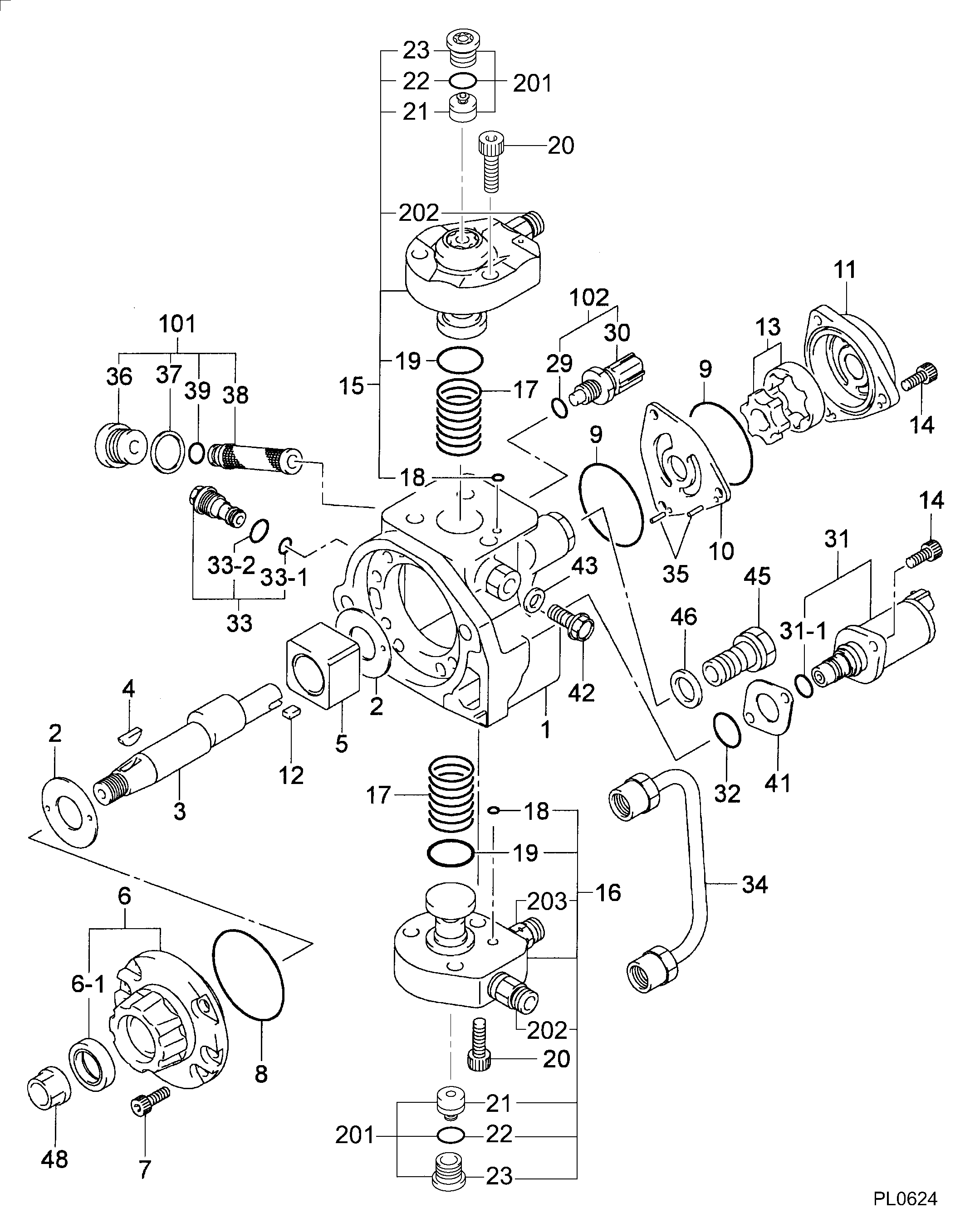
№
Qty
Part num
Name
Remarks
Manufacture num
Cross reference number
Part num
Firm num
Firm
Name
29400-00294
PUMP ASSY, SUPPLY
Information:
The vehicle speed circuit consists of the Vehicle Speed Sensor, the Vehicle Speed Buffer and associated wiring. The sensor is a standard magnetic pickup and is supplied by the truck manufacturer. It senses the movement of teeth on the output shaft of the transmission. The buffer (Caterpillar supplied) takes the signal from the sensor, conditions it and sends it to both the ECM and the vehicle speedometer.There are three acceptable options for wiring of the vehicle speed circuit: For all three options, the Vehicle Speed Buffer should be grounded to the same ground point as the ECM. On 3406B (PEEC III) Engines, the ECM ground point is the cylinder head ground stud.Option 1. Use separate sensors for the Vehicle Speed Buffer and the speedometer, with the second sensor supplying the signal to the speedometer. This option completely isolates the two circuits and is preferred by Caterpillar. See Illustration 1.
Illustration 1
Recommended vehicle speed circuit wiring when using two separate sensors.Option 2. Use a single sensor, with the Vehicle Speed Buffer supplying the signal to the speedometer. This option provides good results when correctly wired. Note that this illustration is electrically identical to the schematic in the 3406B (PEEC III) Diesel Truck Engine Electrical Schematic, Form No SENR5152, which is in the complete Service Manual, 3406B (PEEC III) Diesel Truck Engine, Form No. SENR5150, but shows the required grounding for the speedometer more clearly.The 3E0020 buffer provides a second output line for speedometer requiring two signal lines.
Illustration 2
Recommended vehicle speed circuit wiring using a single sensor.Option 3. Use a dual winding sensor, with the second winding supplying the signal to the speedometer. This option is not preferred by Caterpillar, but can provide acceptable results if the sensor is installed correctly.Dual winding sensors may be used in some new OEM installations which have been specifically reviewed by Caterpillar.
Illustration 3
Recommended vehicle speed circuit wiring when using a dual-winding sensor.The Vehicle Speed Buffer has a five-pin connector (J14/P14) with pins to battery negative, battery positive, the ECM and two for the vehicle speedometer.+ Battery (Pin A) supplies battery power to the buffer.- Battery (Pin B) provides battery ground through the cylinder head ground stud.Buffer Output to the ECM (Pin D) supplies a series of 5 volt DC pulses to the ECM. The frequency of the pulses varies directly with the speed of the vehicle.When a single Vehicle Speed Sensor is used, as in Illustration 2, the vehicle speed signal to the speedometer is provided by the buffer.The 3E0020 buffer has two speedometer outputs, one at P14, Pin C and one at P14, Pin E. Output at each one is a series of -8 volt to +8 volt pulses. The two outputs oppose one another; when Pin C is at +8 volts, Pin E is at -8 volts, and vice versa. Either or both outputs may by used.