29400-00163 PUMP ASSY, SUPPLY Denso Cross


Rating:
70
Buy PUMP ASSY, SUPPLY 29400-00163 genuine, new aftermarket engine parts with delivery

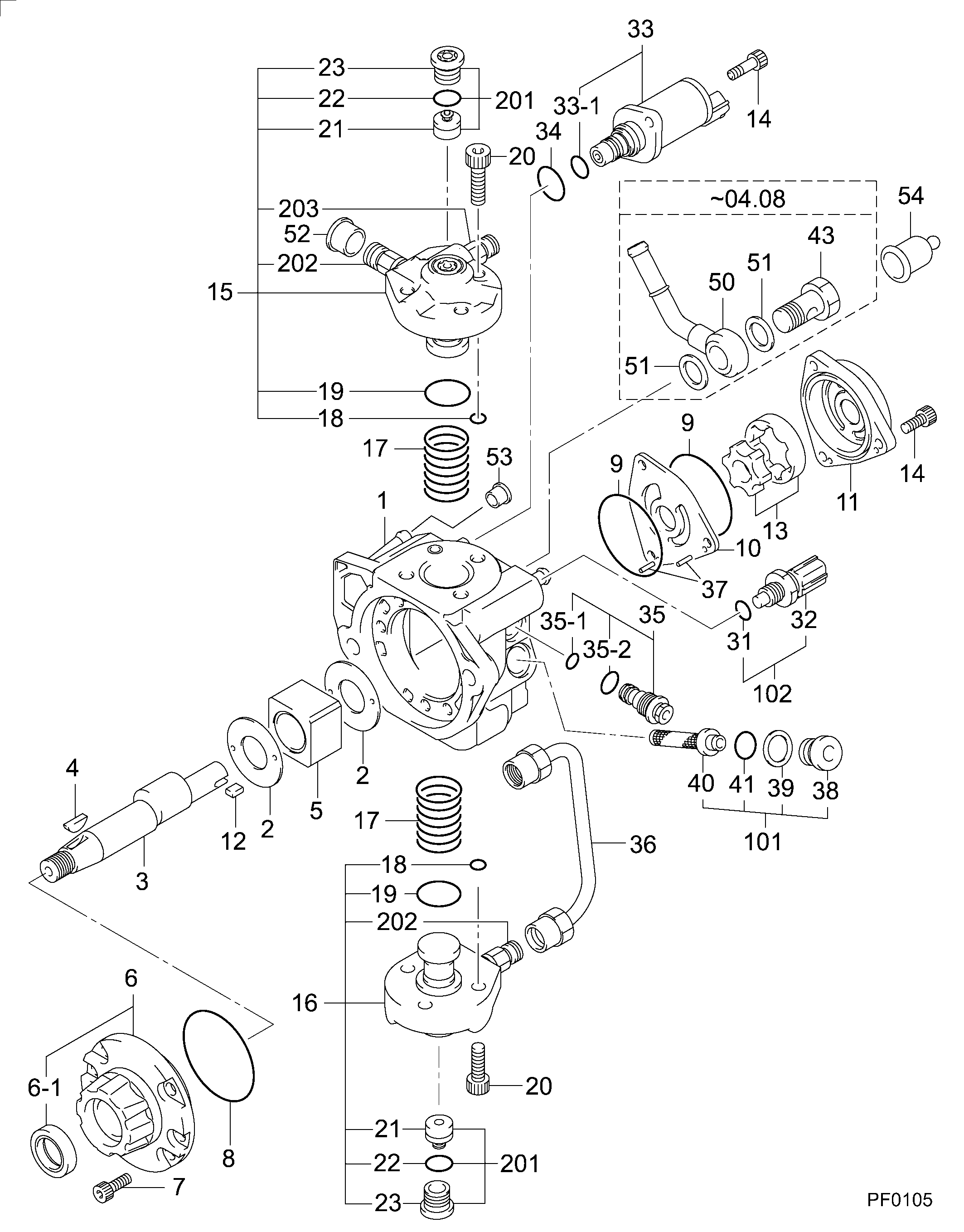
Information pump assy, supply Denso

Components :

00.001
PUMP ASSY, SUPPLY
HP3 -0408
00.001
PUMP ASSY, SUPPLY
HP3 0511-
00.001
PUMP ASSY, SUPPLY
HP3,*1 0408--0511
01.002
OVERHAUL KIT, SUPP
O/H KIT* -1010

Scheme #.#:

Qty
Part num
Name
Remarks
Manufacture num
000
[01]
PUMP ASSY, SUPPLY
HP3 -0408
16700AW420 NISSAN MOTOR
000
[01]
PUMP ASSY, SUPPLY
HP3,*1 0408--0511
16700AW421 NISSAN MOTOR
000
[01]
PUMP ASSY, SUPPLY
HP3 0511-
16700AW42B NISSAN MOTOR
001
[01]
HOUSING SUB-ASSY,
-0408
001
[01]
HOUSING SUB-ASSY,
*1 0408-
002
[02]
WASHER, CAMSHAFT
D44,T1.7
003
[01]
CAMSHAFT, SUPPLY P
004
[01]
KEY, WOODRUFF
W4.00
005
[01]
RING SUB-ASSY, CAM
-0407
005
[01]
RING SUB-ASSY, CAM
0407-
006
[01]
COVER SUB-ASSY, BE
-0511
006
[01]
COVER SUB-ASSY, BE
0511-
006-001
[01]
SEAL, OIL
D30
007
[06]
BOLT, SOCKET
M6,L16
008
[01]
O-RING, SUPPLY PUM
ID53.7
009
[02]
O-RING, SUPPLY PUM
ID51.2
010
[01]
PLATE, FEED PUMP,
-0505
010
[01]
PLATE, FEED PUMP,
0506--0511
010
[01]
PLATE, FEED PUMP,
0511-
011
[01]
COVER, FEED PUMP
012
[01]
KEY, FEED PUMP
013
[01]
ROTOR SET, FEED PU
-0408
013
[01]
ROTOR SET, FEED PU
0408--0506
013
[01]
ROTOR SET, FEED PU
0507-
014
[05]
BOLT, SOCKET
M6,L20
015
[01]
ELEMENT KIT, SUPPL
M14,M12 -0412
015
[01]
ELEMENT KIT, SUPPL
M12X2,*2 0412--1203
015
[01]
ELEMENT KIT, SUPPL
1204-
016
[01]
ELEMENT KIT, SUPPL
M14 -0412
016
[01]
ELEMENT KIT, SUPPL
M12,*2 0412--1203
016
[01]
ELEMENT KIT, SUPPL
1204-
017
[02]
SPRING, PLUNGER
L36.3 -0408
017
[02]
SPRING, PLUNGER
L32.9 0408-
018
[02]
O-RING, SUPPLY PUM
ID5.0
019
[02]
O-RING, SUPPLY PUM
ID28.5
020
[06]
BOLT, SOCKET
M8,L30.5
021
[02]
VALVE SUB-ASSY, SU
NO SUPPLY 1204-
022
[02]
O-RING, SUPPLY PUM
1204-
023
[02]
PLUG, CYLINDER
1204-
031
[01]
O-RING, DISTRIBUTI
ID9.8
032
[01]
SENSOR, FUEL TEMPE
FUEL TEMP.SENSOR -0511
032
[01]
SENSOR, FUEL TEMPE
FUEL TEMP.SENSOR 0511-
033
[01]
VALVE ASSY, SUCTIO
-0511
033
[01]
VALVE ASSY, SUCTIO
0511-
033-001
[01]
O-RING, VALVE
ID10.8
034
[01]
O-RING, SOLENOID
ID22.8
035
[01]
VALVE SUB-ASSY, RE
-0501
035
[01]
VALVE SUB-ASSY, RE
0502-
035-001
[01]
O-RING, SUPPLY PUM
ID 7.5
035-002
[01]
O-RING, SUPPLY PUM
ID10.5
036
[01]
PIPE, SUPPLY PUMP
M14 -0412
036
[01]
PIPE, SUPPLY PUMP
M12,*2 0412-
037
[02]
PIN, STOPPER
L10.5
038
[01]
PLUG, FILTER
M14L15.3
039
[01]
GASKET
ID14.3T1
040
[01]
FILTER SUB-ASSY
041
[01]
O-RING
ID 6.5
043
[01]
SCREW, HOLLOW
M14,L26 -0408
050
[01]
NIPPLE, SWIVEL
-0408
051
[02]
WASHER
T1.4 -0408
052
[01]
PLUG
FOR M12 -0509
052
[01]
PLUG
FOR M12 0509-
053
[01]
COVER, RUBBER
FOR D6.35
054
[01]
CAP
FOR D10 -0509
054
[01]
COVER, RUBBER
FOR D9.89 0509-
101
[01]
OVERHAUL KIT, SUPP
FILTER KIT
102
[01]
OVERHAUL KIT, SUPP
SENSOR KIT
200
[01]
OVERHAUL KIT, SUPP
O/H KIT
201
[02]
OVERHAUL KIT, SUPP
SUCTION 1204-
202
[02]
ELEMENT KIT, SUPPL
1204-
203
[01]
HOLDER, DELIVERY V
1204-

Cross reference number


Part num
Firm num
Firm
Name
29400-00163 
 
PUMP ASSY, SUPPLY


Information:

1. Using Tool (A), remove engine oil filter (1).2. Remove five bolts (2) and the washers that hold the oil filter base to the engine oil cooler. Remove the oil filter base and three O-ring seals. 3. Remove plug (3), valve spring (4) and bypass valve (5) from the oil filter base. Remove the O-ring seal from plug (3).4. Remove the filter stud from the oil filter base. 5. Disconnect tube assembly (6) from the engine oil cooler.6. Remove thirteen bolts (7) and the washers that hold the engine oil cooler to the cylinder block. Remove the oil cooler base and the gasket. 7. Remove plug (8), valve spring (9) and bypass valve (10) from the oil cooler base. 8. Remove oil cooler (11) and the gasket from the cylinder block. Remove the two O-ring seal from the cylinder block. The following steps are for the installation of the engine oil cooler, the oil filter base and the engine oil filter.9. Check the condition of the all O-ring seals and gaskets used in the installation of the engine oil cooler. If any of the parts are damaged, use new parts for replacement.10. Put the two O-ring seals in position in the cylinder block. Put the gasket and engine oil cooler (11) in position in the cylinder block.11. Install the O-ring seal on plug (8).12. Apply clean engine oil on the components of the oil cooler bypass valve. Install bypass valve (10), valve spring (9) and plug (8) in the oil cooler base.13. Put the gasket and oil cooler base in position over the engine oil cooler. Install thirteen bolts (7) and the washers that hold the engine oil cooler to the cylinder block.14. Connect tube assembly (6) to the engine oil cooler.15. Install the O-ring seal on plug (3).16. Apply clean engine oil on the components of the oil filter bypass valve. Install bypass valve (5), valve spring (4) and plug (3) in the oil filter base.17. Put 9S3263 Thread Lock on the last 7.5 1.5 mm (.30 .06 in) of the threads at the base end of the filter stud. Install the filter stud in the oil filter base. Tighten the filter stud to a torque of 68 7 N m (50 5 lb ft).18. Install the three O-ring seals in the oil filter base. Put the oil filter base in position on the engine oil cooler. Install the five washers and bolts (2) that hold it.19. Install a new engine oil filter (1). See the topic "Engine Oil And Filter(s)" in the 3114 & 3116 ATAAC Diesel Truck Engine Operation & Maintenance Manual, Form No. SEBU6723 for details regarding filter installation and service intervals.

Have questions with 29400-00163?


Group cross 29400-00163

Back to top