Rating:
Information pump assy, injecti Denso
Product
Fuel Injection Pump
Vehicle engine
INDUSTRIAL D070
Engine
D070
Serial start-end
0707-
Info
850D
Injector Nozzle
093500-8160
Injector nozzle:
0935008160
KIT List:
Part name
Kit1
Kit2
Components :
Scheme #.#:
№
Qty
Part num
Name
Remarks
Manufacture num
000
[01]
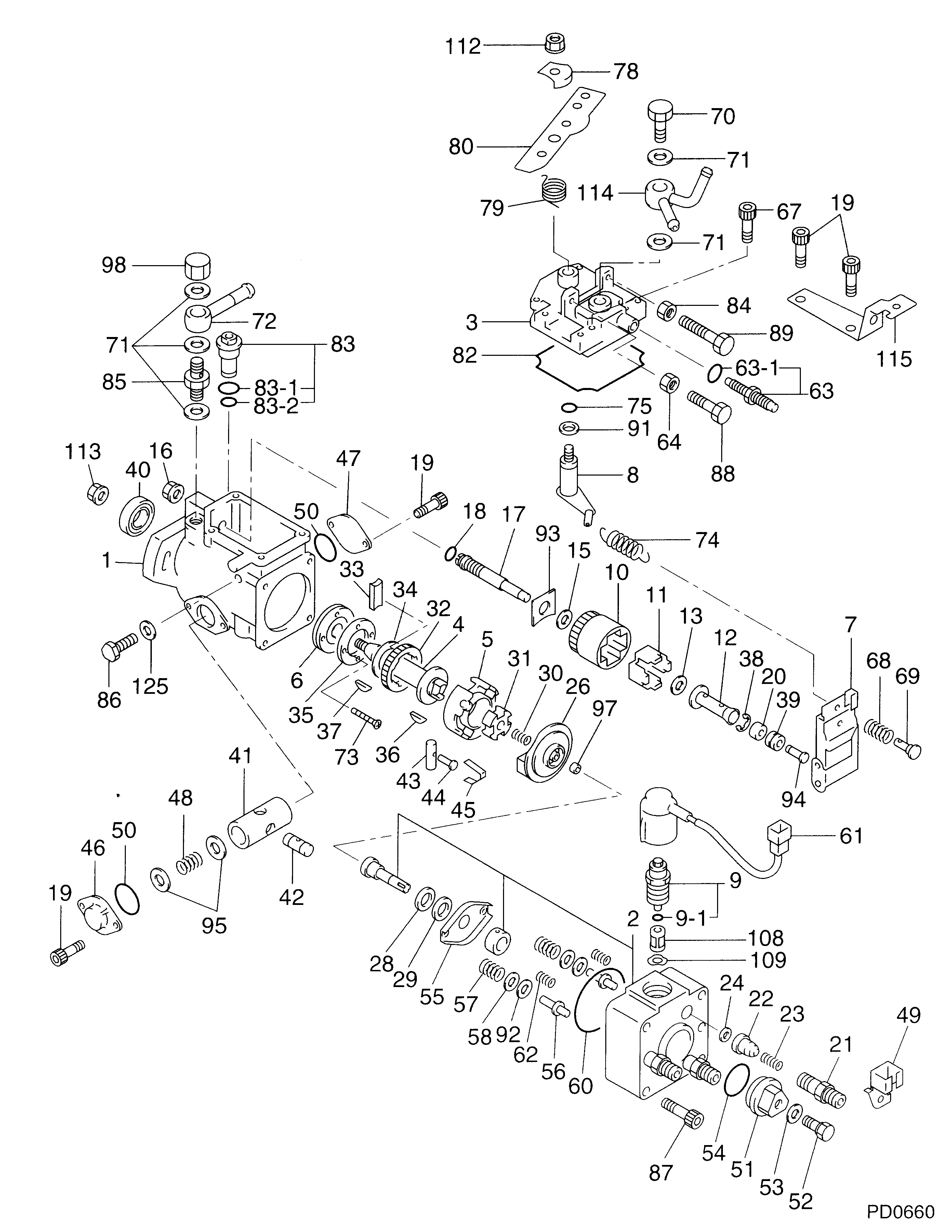
19600-05960
PUMP ASSY, INJECTI
Include in ##:
19600-05960
as PUMP ASSY, INJECTI
Cross reference number
Part num
Firm num
Firm
Name
19600-05960
PUMP ASSY, INJECTI
Information:
The water cooled air compressor receives coolant through a tube that is connected to the water manifold in the side of the cylinder block. Coolant returns through a tube from the air compressor head to the diesel engine cylinder head.Until the coolant reaches the temperature required to open the temperature regulator, coolant bypasses the radiator and flows directly back to the water pump.When the coolant reaches the temperature required to open the temperature regulator, coolant is then directed through the radiator.A pressure relief cap assembly is used to control the pressure in the cooling system, and prevents loss of coolant through the radiator overflow tube.Pressurizing the cooling system serves two purposes. First, it permits safe operation at coolant temperatures higher than the normal boiling point, providing a margin of cooling for intermittent peak loads. Secondly, it prevents cavitation in the water pump, and reduces the possibility of air or steam pockets forming in the coolant passages. Proper operation of the pressure relief cap assembly is essential. A pressure relief cap allows pressure (and some water, if the cooling system is too full) to escape when the pressure in the cooling system exceeds the capacity of the pressure cap. Loss of pressure will cause steam to form when coolant temperature is above the normal boiling point.Water Pump
The centrifugal-type water pump has two seals, one prevents leakage of water and the other prevents leakage of lubricant.An opening in the bottom of the pump housing, allows any leakage at the water seal or the rear bearing oil seal to escape.Fan
The fan is driven by three V-belts, from a pulley on the crankshaft. Belt tension is adjusted by moving the bracket assembly which includes the fan mounting and pulley.Water Temperature Regulator
The water temperature regulator restricts the flow of coolant through the radiator, until the coolant reaches operating temperature; approximately 165°F (74°C.) The regulator is fully open at approximately 180°F (82°C.)The shunt cooling system is used in many truck installations. The shunt cooling system provides continuous circulation which helps prevent aeration and pump cavitation by maintaining a positive head of water at the pump inlet at all times. It differs from the conventional cooling system in that the radiator top tank is divided into two compartments (upper and lower) with a small air/coolant bleed tube connecting them. A shunt line located as low as possible in the upper chamber directs coolant to the pump inlet. When the coolant reaches the temperature required to open the thermostat, coolant is directed into the bottom chamber of the radiator top tank, down through the radiator core to the suction line of the pump and then to the engine. Coolant, which may contain some air will flow from the bottom chamber to the top chamber through the small air/coolant bleed tube. The air will separate from the water in the upper chamber. The water will flow out the shunt line and the air will remain in the upper chamber until excessive pressure is built up, at which