Rating:
Information pump assy, injecti Denso
Product
Fuel Injection Pump
Vehicle engine
L200/TRITON 4D56
Engine
4D56
Serial start-end
9811--0008
Info
Injector Nozzle
093500-6210
Injector nozzle:
0935006210
KIT List:
Part name
Kit1
Kit2
Components :
Scheme #.#:
№
Qty
Part num
Name
Remarks
Manufacture num
000
[01]
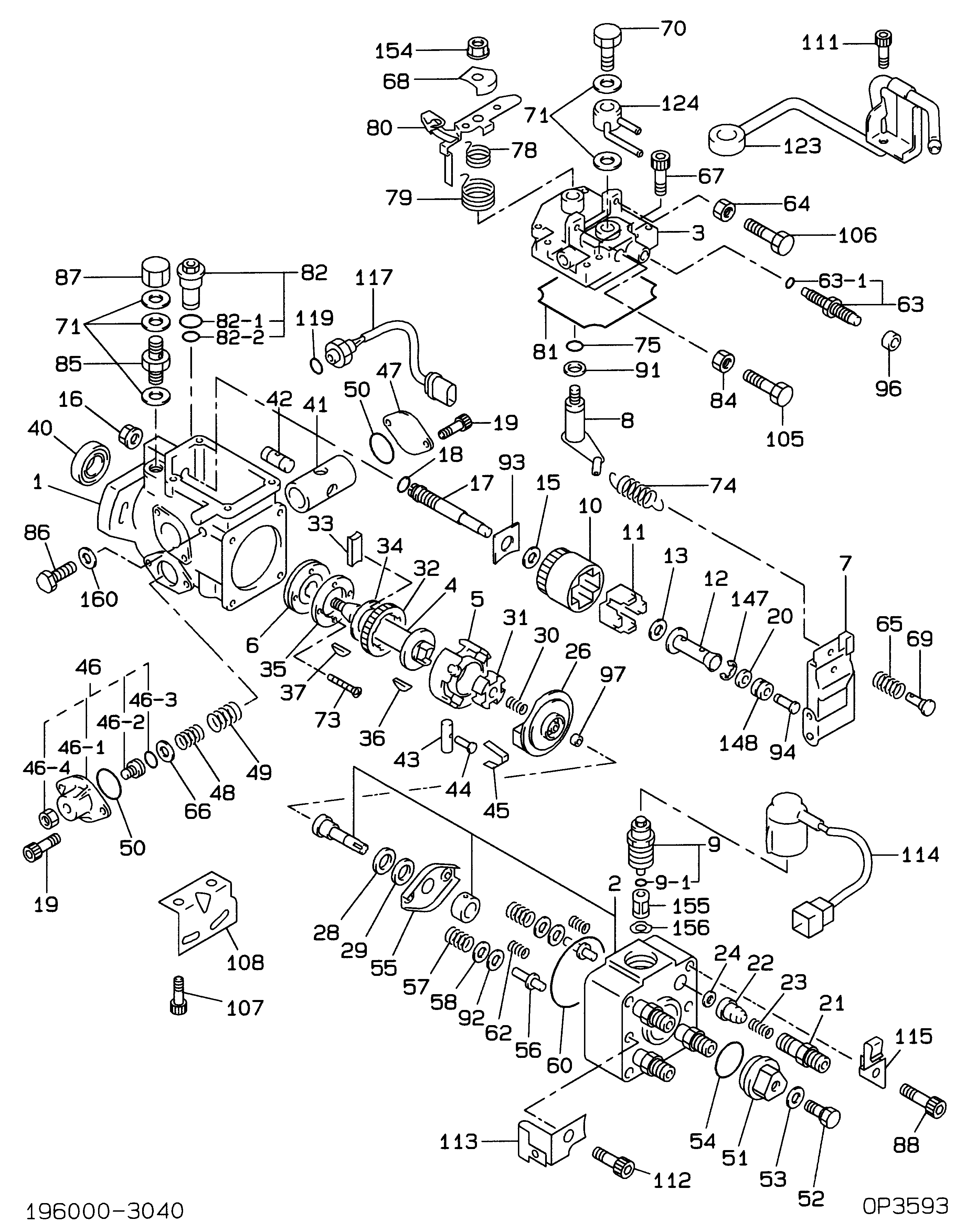
19600-03040
PUMP ASSY, INJECTI
Include in ##:
19600-03040
as PUMP ASSY, INJECTI
Cross reference number
Part num
Firm num
Firm
Name
19600-03040
PUMP ASSY, INJECTI
Information:
2. Turn the crankshaft until two of the pistons are at bottom center. Remove the nuts and bolts (1) from the connecting rods that are at bottom center. Remove connecting rod caps (2). Put identification marks on them for installation purposes.
Do not let the connecting rods hit the crankshaft or the bottom edge of the cylinder liners when the pistons are removed.
3. Push the connecting rods and pistons away from the crankshaft until the piston rings are out of the cylinder liners. Remove the two pistons from the engine.4. Keep each connecting rod cap with its respective connecting rod and piston. Put identification marks on each piston as to its location in the engine.5. Do Steps 1 through 4 for the removal of the remaining pistons.Install Pistons & Connecting Rods
1. Turn the crankshaft until the bearing journals for the pistons to be installed are at bottom center.2. Put clean engine oil on the crankshaft journals and on the inside of the cylinder liners. Put clean engine oil on the piston rings and the connecting rod bearings.3. Move the piston rings on the pistons until the ring openings are approximately 90° apart. 4. Put the piston in the cylinder liner with the "V" mark on the piston in alignment with the "V" mark on the cylinder block. Put Tool (A) in position on the cylinder block and compress the piston rings.5. Push the piston into the cylinder liner and out of the ring compressor. 6. Pull the connecting rod into position on the crankshaft as shown. Install connecting rod bolts (1) in the connecting rods.7. Put clean engine oil on the lower half of the connecting rod bearing. Put 2P2506 Thread Lubricant on the bolt threads and on the surfaces of the nuts that make contact with the connecting rod caps.
When the connecting rod caps are installed, make sure the number on the side of the cap is next to and respective with the number on the side of the connecting rod.
8. Install connecting rod caps (2) and the nuts that hold them. Tighten the nuts to a torque of 40 4 N m (30 3 lb ft). Put a mark on each nut as to its location. Tighten them 90° 5° more.9. Do Steps 1 through 8 for the remainder of the pistons.End By:a. install oil pumpb. install oil pan platec. install cylinder head assembly and spacer plateDisassemble Pistons & Connecting Rods
Start By:a. remove pistons and connecting rods 1. Remove the rings from the pistons with Tool (A). 2. Remove retaining ring (3), piston pin (1) and connecting rod (2) from the piston.3. Remove the bearings from the crankshaft end of the connecting rod.4. See Use Of Piston Pin Bearing Removal And Installation Tools, Special Instructions, Form No. SMHS7295-02 for more information about removal and installation of piston pin bearings. Be sure to remove the bearings from the crankshaft end of connecting rod.5. Heat the connecting rod in an oven to a temperature of 176