Rating:
Information pump assy, injecti Denso
Product
Fuel Injection Pump
Vehicle engine
GALANT 4D68T
Engine
4D68T
Serial start-end
9701-
Info
Injector Nozzle
093500-5450
Injector nozzle:
0935005450
KIT List:
Part name
Kit1
Kit2
Components :
Scheme #.#:
№
Qty
Part num
Name
Remarks
Manufacture num
000
[01]
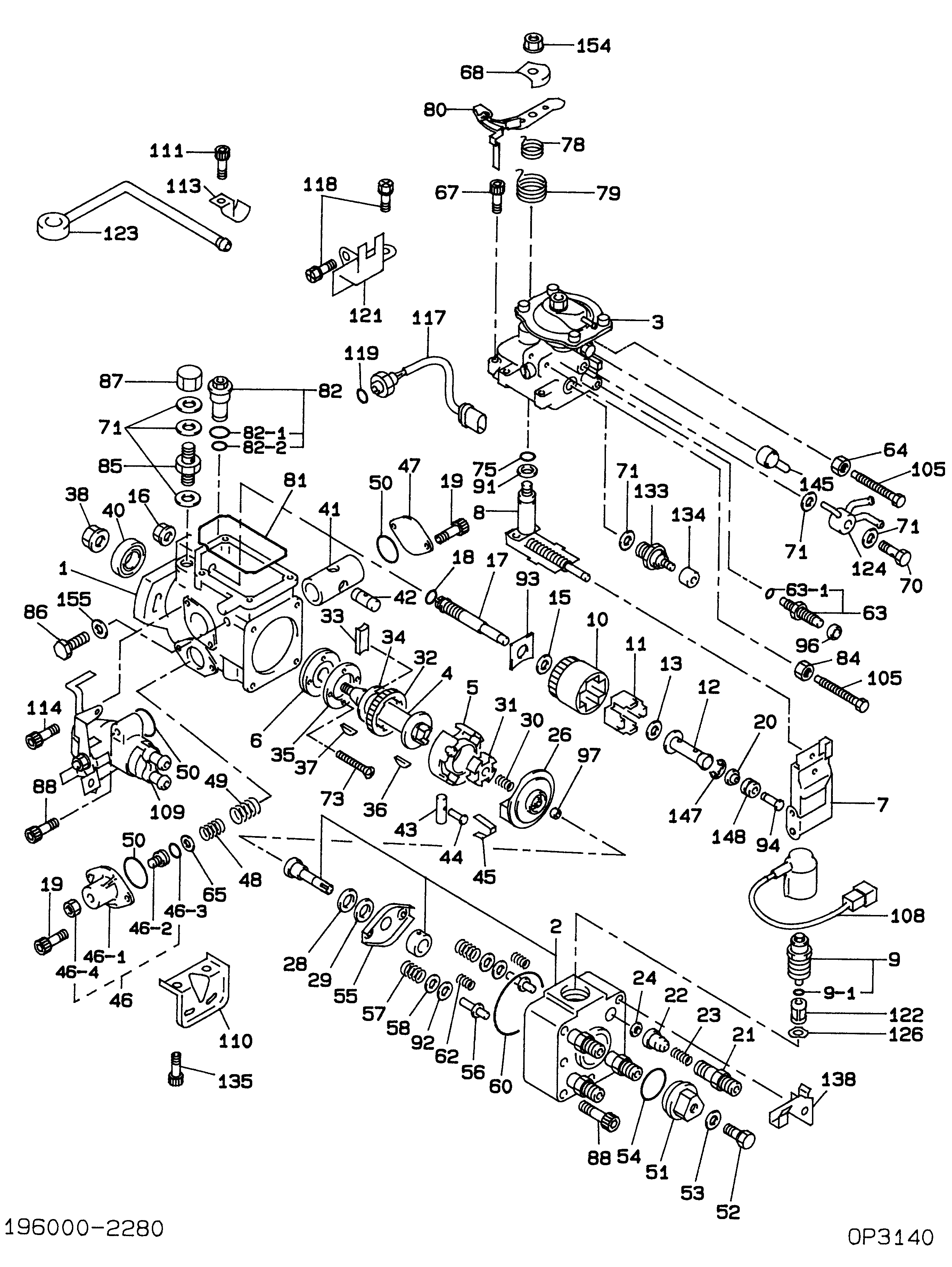
19600-02280
PUMP ASSY, INJECTI
Include in ##:
19600-02280
as PUMP ASSY, INJECTI
Cross reference number
Part num
Firm num
Firm
Name
19600-02280
PUMP ASSY, INJECTI
Information:
Do not let the retaining compound get into the compressor wheel bore or on the shaft, because it can make removal of the compressor wheel difficult during future turbocharger disassembly.
C. Put a small amount of lubricant, such as Lubriplate, on the nut seat area on the compressor. Do not put lubricant on the threads.D. Tighten the compressor wheel retainer nut to ... 30 3 N m (264 24 lb in)
Do not bend or add stress to the shaft when nut is tightened.
(7) Bore in housing (new) ... 22.255 to 22.268 mm (.8762 to .8767 in) Outside diameter of the bearing (new) ... 22.144 to 22.154 mm (.8718 to .8722 in)Maximum permissible clearance between bearing and bore in housing (worn) ... 0.15 mm (.006 in)(8) Thickness of each thrust ring ... 2.553 0.013 mm (.1005 .0005 in)(9) Put 5P3931 Anti-Seize Compound on threads and tighten bolts that hold turbocharger to manifold to ... 55 5 N m (40 4 lb ft)Schwitzer S4D
(1) End play for shaft (new) ... 0.114 0.038 mm (.0045 .0015 in) Maximum permissible end play (worn) ... 0.20 mm (.008 in)(2) Thickness of thrust bearing (where thrust rings contact bearing) ... 5.36 0.03 mm (.211 .001 in)(3) Bore in housing (new) ... 24.994 to 25.006 mm (.9840 to .9845 in) Outside diameter of the bearing (new) ... 24.882 to 24.892 mm (.9796 to .9800 in)Maximum permissible clearance between bearing and bore in housing (worn) ... 0.15 mm (.006 in)(4) Maximum permissible gap of oil seal ring, measured in bore of housing ... 0.25 mm (.010 in)(5) Install the compressor wheel (at room temperature) as follows: a. Put the compressor wheel in position on the shaft.b. Put a small amount of clean engine oil on the shaft threads.c. Install the nut on the shaft, and tighten the nut to a torque of 14 to 17 N m (125 to 150 lb in).
Do not bend or add stress to the shaft when nut is loosened or tightened.
d. Remove nut from shaft and apply 6V1541 Quick Cure Primer on the threads of the shaft and nut followed by application of 9S3265 Retaining Compound.e. Install the nut on the shaft, and tighten the nut to a torque of 4 N m (30 lb in).f. Tighten nut more as follows: For 99.0 mm (3.90 in) diameter compressor wheels, tighten the nut an additional 90°.For 86.4 mm (3.40 in) diameter compressor wheels, tighten the nut an additional 60°.(6) Tighten both band clamps with procedure that follows: a. Tighten to ... 14 1.1 N m (125 10 lb in)b. Tap (hit) clamp lightly all around.c. Tighten again to ... 14 1.1 N m (125 10 lb in)
Do not overtighten the clamps.
(7) Thickness of each thrust ring ... 2.553 0.013 mm (.1005 .0005 in)(8) Diameter of shaft (new) ... 15.997 to 16.005 mm (.6298 to .6301 in) Bore in the bearing (new) ... 16.035 to 16.043 mm (.6313