Rating:
Information pump assy, injecti Denso
Product
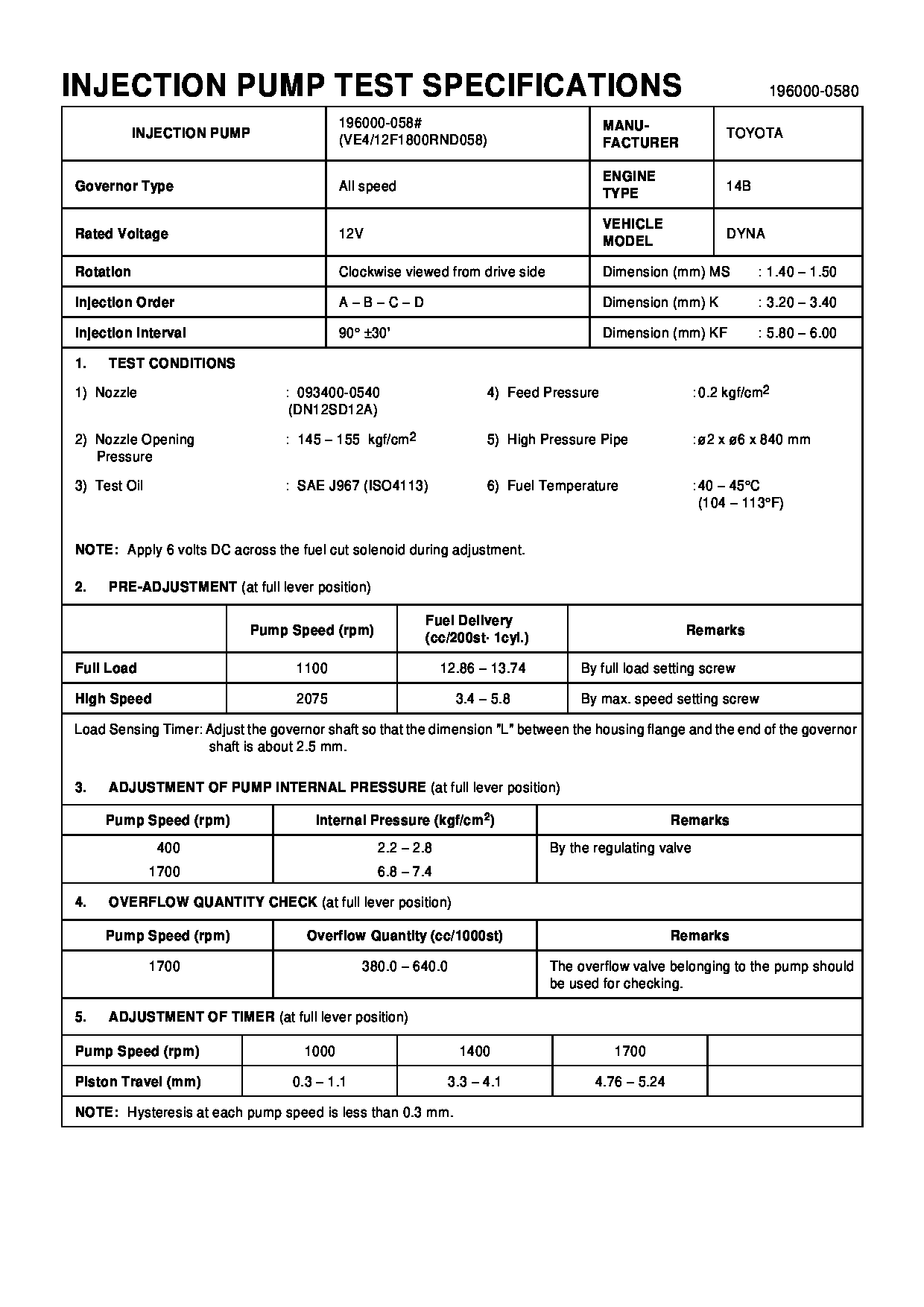
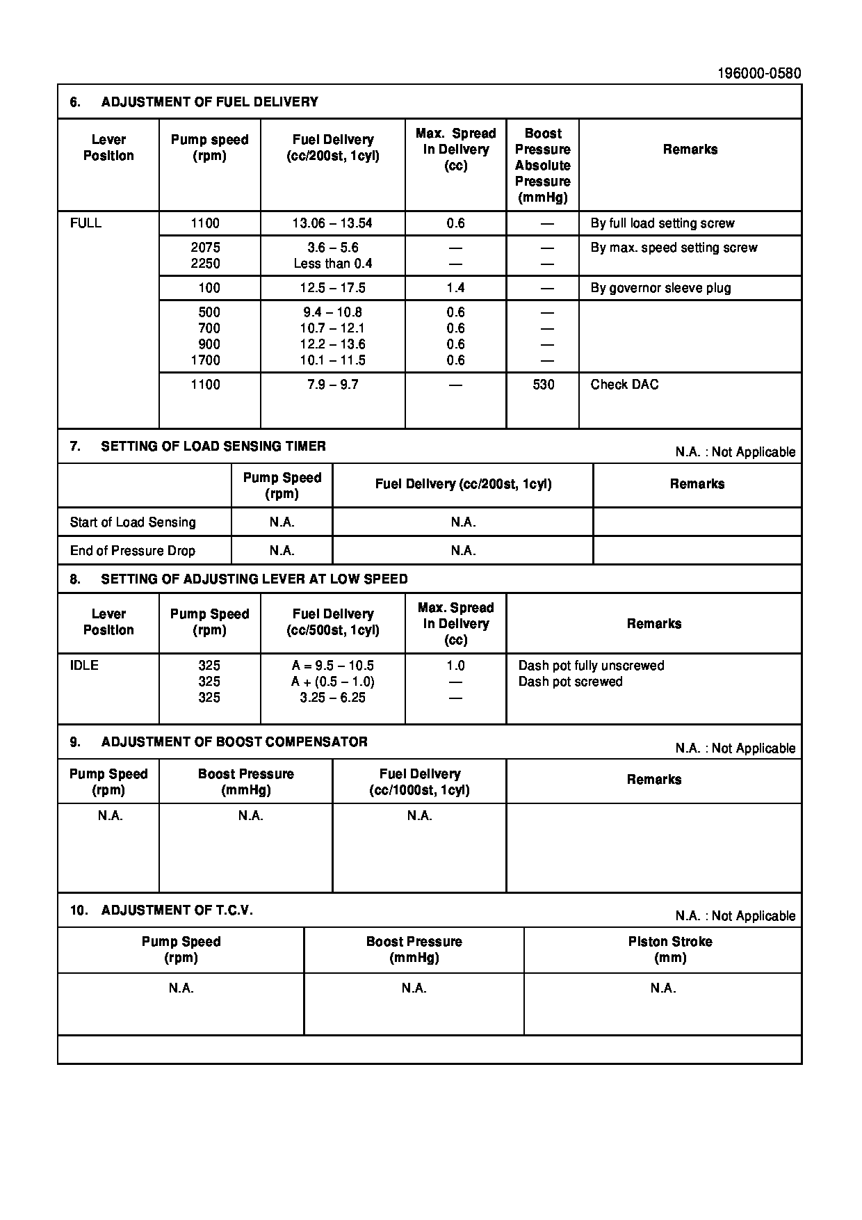
Fuel Injection Pump
Vehicle engine
DYNA 14B
Engine
14B
Serial start-end
9508-
Info
Injector Nozzle
093500-4060
Manufacture:
22100-58641 TOYOTA
Dim 1
3.2-3.4
Dim 2
5.8-6.0
Dim 3
0.2-0.4
Dim 4
Dim 5
Dim 6
Information
Injector nozzle:
0935004060
KIT List:
Part name
Kit1
Kit2
Compare Prices: .
As an associate, we earn commssions on qualifying purchases through the links below

Diesel Common Rail Injection Pump 22100-58641 Replacement 196000-0580
PANQIUZ Made of durable plastic and metal, this fuel pump assembly ensures the service life and reliability || The electric fuel pump has excellent design and stable operation, which reduces the risk of mechanical failure and improves the overall reliability || Efficient gasoline inhalation and injection design ensures that the fuel pump assembly has the best engine performance || The simple structure of electric fuel pump makes maintenance more convenient and reduces the maintenance cost of long-term operation || Diesel Common Rail Injection Pump 22100-58641 Replacement 196000-0580
PANQIUZ Made of durable plastic and metal, this fuel pump assembly ensures the service life and reliability || The electric fuel pump has excellent design and stable operation, which reduces the risk of mechanical failure and improves the overall reliability || Efficient gasoline inhalation and injection design ensures that the fuel pump assembly has the best engine performance || The simple structure of electric fuel pump makes maintenance more convenient and reduces the maintenance cost of long-term operation || Diesel Common Rail Injection Pump 22100-58641 Replacement 196000-0580
Components :
Scheme #.#:

№
Qty
Part num
Name
Remarks
Manufacture num
000
[01]
19600-00580
PUMP ASSY, INJECTI
22100-58641
TOYOTA
Include in ##:
19600-00580
as PUMP ASSY, INJECTI
Cross reference number
Part num
Firm num
Firm
Name
19600-00580
22100-5864
PUMP ASSY, INJECTI
1960000580
22100-58641
TOYOTA
PUMP ASSY, INJECTI
Information:
Adjust
1. The ejector should operate freely without binding. To adjust the guide rollers, loosen the roller shaft clamping bolt. 2. Turn the roller (eccentric) shaft to position the roller. 3. Tighten the clamping bolt. Clearance between the guide rollers and the scraper bowl should be 3.00 to 20.00 mm (.118 to .787 in).Ejector Carrier Rollers
(631 & 637)
Adjust
1. The ejector should operate freely without dragging. To adjust the carrier rollers, loosen the clamping bolt. 2. Turn the roller (eccentric) shaft to position the roller.3. Tighten the clamping bolt. Clearance between the bottom of the ejector and the bottom of the bowl should be 1.0 to 13.0 mm (.04 to .50 in).Ejector Support Rollers
(631 & 637)
Adjust
1. The ejector should operate freely without dragging. To adjust the carrier rollers, loosen the clamping bolt. 2. Turn the roller (eccentric) shaft to position the roller. 3. Tighten the clamping bolt. The distance between rollers, outside to outside, should be .00 to 6.00 mm (.00 to .236 in) less than the narrowest dimension between the roller guide tracks.Refer to the Service Manual for your machine or contact your Caterpillar dealer for the correct adjustment procedure.Ejector Carriage Rollers
(639)
Adjust
Do not get under the push frame unless the front engine is stopped and the ejector floor is blocked.
1. Install pin in the position that will block movement of the carriage.See "Blocking the Ejector Floor Closed" in the "Safety" section of the Operation (Operator's) Guide. 2. The carriage should operate freely without binding. To adjust the carriage rollers, loosen the roller shaft clamping bolt. 3. Turn the roller (eccentric) shaft to position the rollers. 4. Tighten the clamping bolt. The distance between rollers, outside to outside, should be .00 to 1.50 mm (.00 to .060 in) less than the narrowest dimension between the guide tracks on the push frame.