Rating:
Information pump assy, injecti Denso
Product
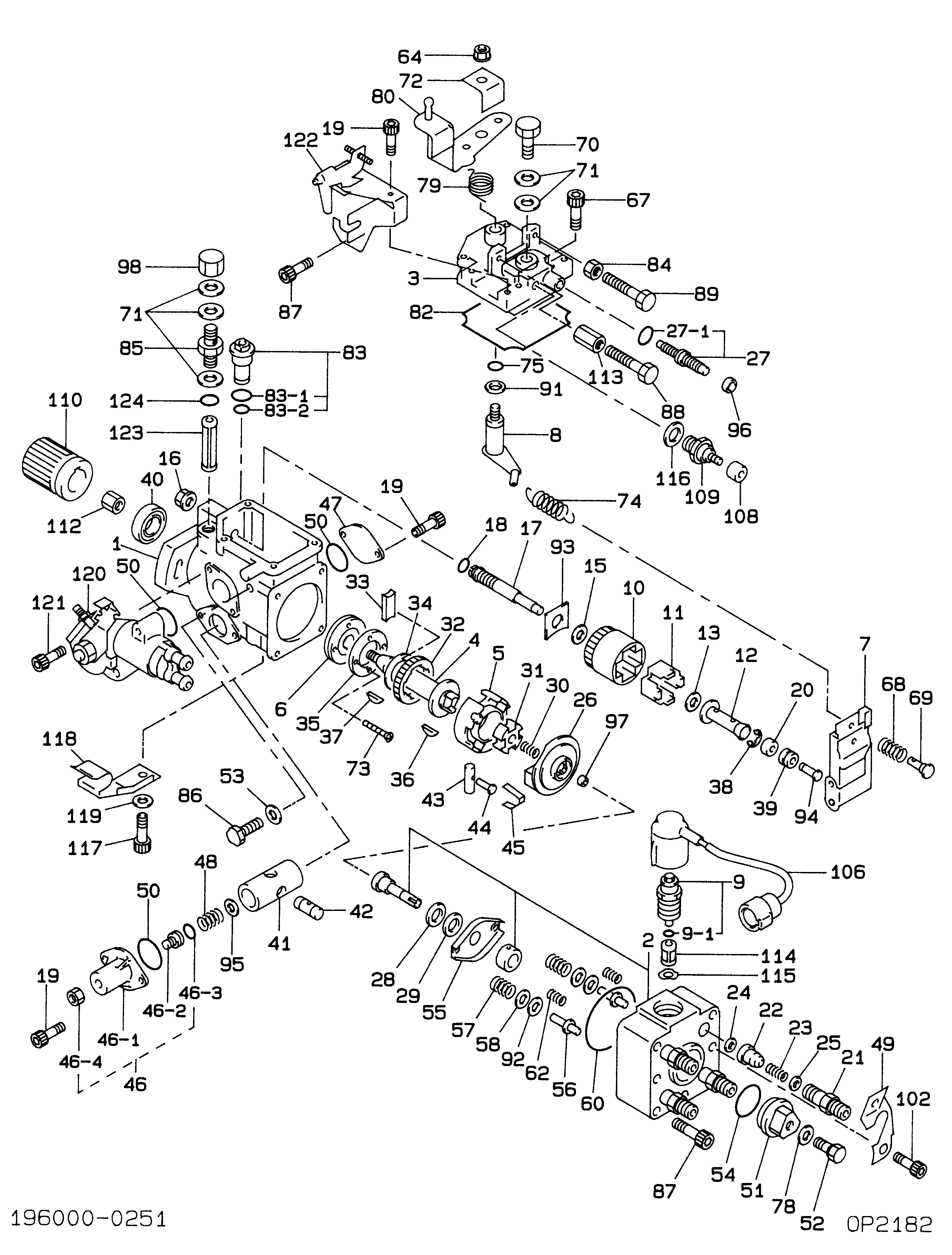
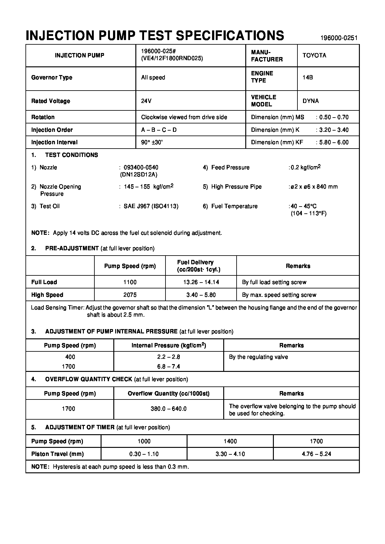
Fuel Injection Pump
Vehicle engine
DYNA 14B
Engine
14B
Serial start-end
9502--9710
Info
Injector Nozzle
093500-4060
Manufacture:
22100-5C250 TOYOTA
Dim 1
3.2-3.4
Dim 2
5.8-6.0
Dim 3
0.5-0.7
Dim 4
Dim 5
Dim 6
Information
Injector nozzle:
0935004060
KIT List:
Part name
Kit1
Kit2
Components :
Scheme #.#:
№
Qty
Part num
Name
Remarks
Manufacture num
Cross reference number
Part num
Firm num
Firm
Name
19600-00250
PUMP ASSY, INJECTI
1960000250
22100-5C250
TOYOTA
PUMP ASSY, INJECTI
Information:
1. Remove four bolts and shield (1). Remove two bolts and screen (2). Disconnect ground strap (3) from the generator mounting bracket. Remove two generator mounting bolts (4). 2. Loosen front engine mounting bolts (5) to provide clearance to raise the rear of the engine. 3. Attach a hoist to generator (6). Raise the generator and the engine so the generator mounting pads are off of the supports. Put blocks under the flywheel housing to support the rear of the engine as shown. 4. Remove bolts (7) that hold fan (9) to the flywheel. Remove bolts (8) that hold the generator housing to the flywheel housing and remove the generator. The weight of the generator is approximately 1130 kg (2500 lb.).Connection Of Engine And Generator (Prime)
The following procudure applies to the 3406B Standby Generator also. 1. Remove the protection material (compound) from the flywheel pilot bore (10) and from the surface (11) that makes contact with the coupling. All contact surfaces of the engine, coupling and generator must be completely clean. 2. Install tooling (A) as shown on the front of the engine with the tip of the indicator on the face of crankshaft pulley (12). Use a bar between the flywheel and flywheel housing to push the crankshaft toward the flywheel to remove all end play. Put the dial indicator in the "zero" position. Move the crankshaft to its most forward position, and make a record of the Total Indicator Reading (TIR). The TIR is the end play of the crankshaft. 3. Put plate assembly (13) in position in the bore of the flywheel to check for clearance. There must be clearance between the outside diameter of the plate assembly (13) and the inside diameter of the bore in the flywheel.
Damage to the engine and/or generator can be the result if the electric set is run with a plate assembly that does not have this clearance.
4. Install full shim pack (14) and plate assembly (13) on the generator with bolts (15).5. Install a guide bolt in the flywheel. Put the generator in position on the engine, and install bolts (7) and (8).6. Use tooling (A) to check crankshaft end play. Do not use force to hold the crankshaft in position. Remove the generator. Remove only enough shims to get the original amount of end play as shown in Step 2. The minimum crankshaft end play should be 0.15 mm (0.006 in.).7. Install the generator and check the crankshaft end play again. If the end play is correct, attach a hoist to the generator and remove the blocks from under the flywheel housing.8. Lower the generator on to the supports and install bolts (4). Connect ground strap (3) to the generator. Install screen (2) and shield (1).9. Tighten fron engine mounting bolts (5).End By:a. install control panel enclosure