Rating:
Information pump assy, injecti Denso
Product
Fuel Injection Pump
Vehicle engine
INDUSTRIAL 1Z
Engine
1Z
Serial start-end
9203-
Info
Injector Nozzle
093500-3430
Injector nozzle:
0935003430
KIT List:
Part name
Kit1
Kit2
Components :
Scheme #.#:
№
Qty
Part num
Name
Remarks
Manufacture num
000
[01]
19100-09940
PUMP ASSY, INJECTI
A4,RSV
22100-78307-71
TOYOTA
Include in ##:
19100-09940
as PUMP ASSY, INJECTI
Cross reference number
Part num
Firm num
Firm
Name
19100-09940
22100-7830
PUMP ASSY, INJECTI
1910009940
22100-78307-71
TOYOTA
PUMP ASSY, INJECTI

Information:
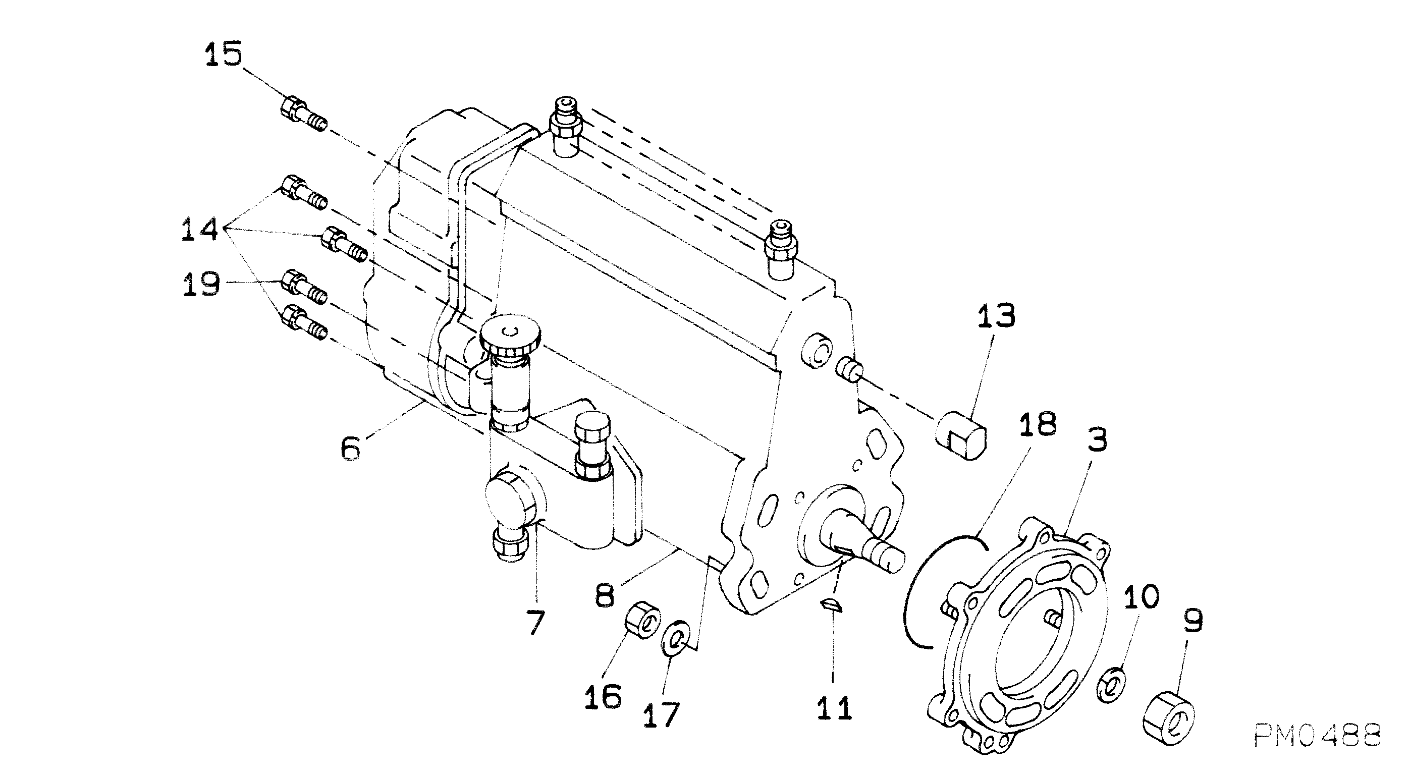
1. Remove bolt (1), six bolts (2), two top bolts (3), housing (4) and the gasket. 2. Remove governor spring (5), the two wave washers, one flat washer and seat from the guide in the housing. 3. Remove bolts (6), cover (7) and the gasket from the housing. Use tooling (A) to remove seal (8) from the cover. 4. Remove low idle adjustment screw (9) and spring (10) from the housing. 5. Remove shaft assembly (12), lever (11) and lever (13) from the housing. 6. Remove two snap rings from pins (15) and remove pins (15). Remove plates (14) and stop (16) from the shaft assembly. 7. Remove pin (18), pin (17) and spring (19) from the shaft assembly. 8. Remove shaft (20) and lever (21) from the housing.
Remove check valve (22) only if a replacement is necessary because the check valve will be damaged during removal.
9. Remove check valve (22) if a replacement is necessary. 10. Remove contact (23) and body (24) for the governor dashpot adjustment screw from the housing.11. Remove bolts (25), cover (26) and the gasket from the housing. 12. Remove seal (27) and adjustment screw (28) for the high idle. 13. Remove two bolts (29), housing (30) and the gasket from the fuel injection pump housing. 14. Remove bolts (31) and torque control group (32).15. Disassemble the torque control group and inspect the spacer, spring and insulator for damage or wear. 16. Remove bolts (33) and block (34) for the full load stop from the housing. 17. Remove the bolt that holds collar (35) to bolt (37). Remove collar (35), collar (36) and the spring from bolt (37). Remove bolt (37) from the block.18. Remove the stop screws from collar (35) if a replacement is necessary. 19. Remove bolts (39) and governor servo (38) from the fuel injection pump. 20. Remove lockring (44), seat (43), spring (broken link spring) (42) and sleeve (41) from valve (40). Remove the other lockring (44) from the groove in the center of valve (40). 21. Remove valve (40), sleeve (45) and piston (47) from the governor servo. Remove the O-ring seal from sleeve (45).22. Remove pin (46) and lever (48) from the governor servo. 23. Use tool (B) to hold spring (50) in compression so ring (49) can be removed. Spring (50) is used to put a preload on the thrust bearing for the camshaft in the fuel injection pump housing.24. Remove ring (49) then remove tool (B).25. Remove bearing (51), sleeves (52) and spring (50) from the governor shaft. 26. Remove ring (53) and dashpot assembly (54) from the governor shaft. 27. Use tool (C) to remove snap ring (60) from seat (57). Remove ring (59) and spool (58) from seat (57).28. Remove seat (57) from spring (56) and remove spring (56) from seat (55). 29. Remove spring (overfueling spring) (61) and riser (62) from the governor shaft. 30. Remove ring (63), races (64) and bearing (65) from the riser. 31. Use a screwdriver to remove