Rating:
Information pump assy, injecti Denso
Components :
Scheme #.#:
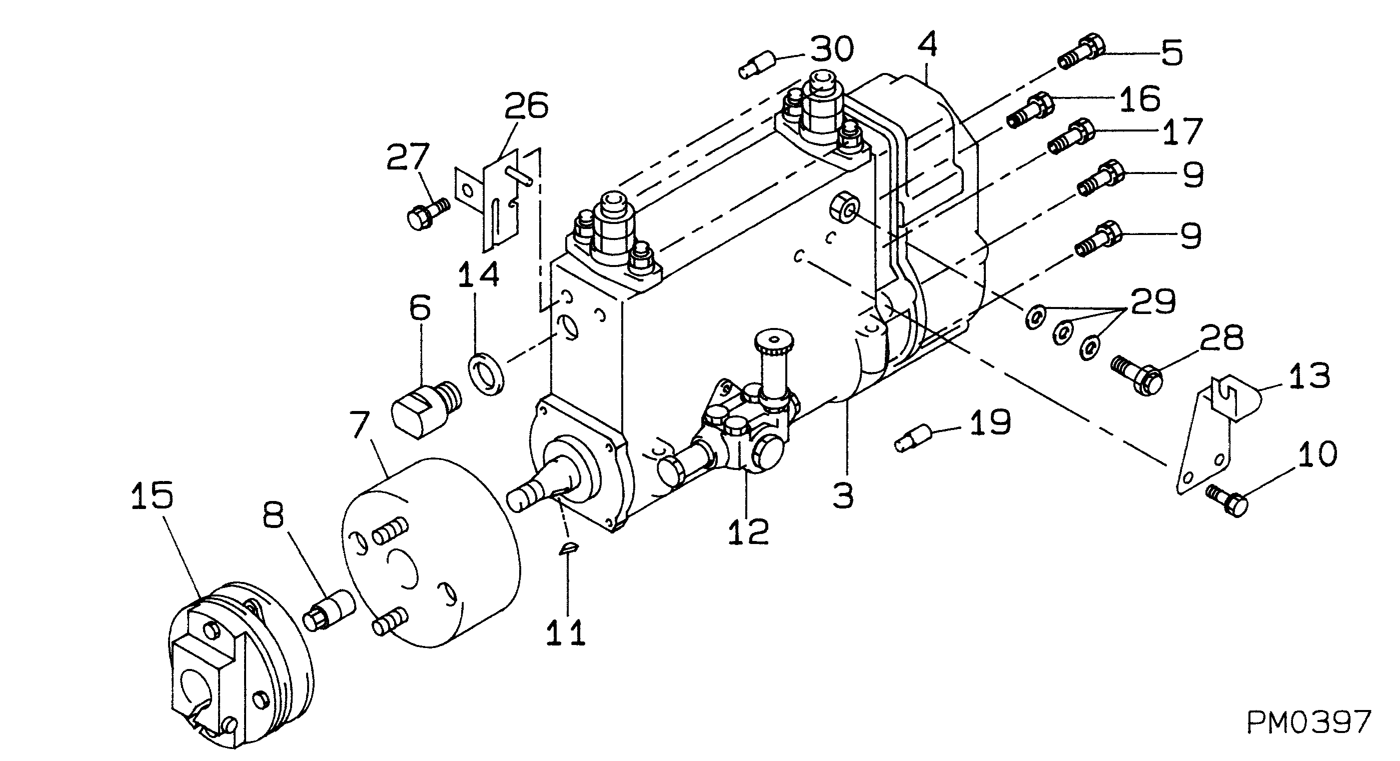
№
Qty
Part num
Name
Remarks
Manufacture num
000
[01]
19100-09812
PUMP ASSY, INJECTI
NB6.R901
22010-6922
HINO
Include in ##:
19100-09812
as PUMP ASSY, INJECTI
Cross reference number
Part num
Firm num
Firm
Name
19100-09812
22010-6922
PUMP ASSY, INJECTI

Information:
CAMSHAFT LOBE
A. Lobe lift. B. Lobe height. C. Base circle.With camshaft installed in the cylinder block, check end play. End play with new components should be .007 .003 in. (0.18 0.08 mm). The maximum permissible end play is .020 in. (0.51 mm).Camshaft Followers
Use an 8S2293 Magnet to remove the cam followers.
REMOVING CAM FOLLOWERSCam followers establish a wear pattern with the camshaft lobes. Identify and reinstall the followers removed. Dishing or circular wear pattern is allowed on the cam follower face, providing the wear face keeps a polished appearance. Replace the follower if the wear face is rough or shows signs of scuffing. A new follower can be used with an old camshaft, providing the lobe is in good condition. Put engine oil on the cam followers and the camshaft lobes before installing the cam followers. Use new cam followers with a new camshaft.Camshaft Gears
1. Remove screw (1) and washer (2) from end of camshaft.
REMOVING TIMING ADVANCE RETAINING SCREW
1. Screw. 2. Washer.2. Remove timing advance unit from the camshaft.3. Install puller (A), with spacer (C) over the shaft in the camshaft spacer (B) on spacer (C) as shown and remove the gear from the camshaft.
REMOVING GEAR (Typical Example)
A. 1P2321 Puller. B. 8S5579 Spacer. C. 9S9155 Spacer.To install the gear use the following procedure:1. Heat the gear to a temperature of approximately 400°F (204°C) before installing on the camshaft.
Do not heat the gear with a torch. Do not heat the gear to a temperature of more than 600°F (315°C). Heating the gear with a torch or to a temperature of more than 600°F (315°C) may cause the two drive dowels for the automatic timing advance to loosen and come out of the gear.
2. Align slot in gear hub with the pin in the camshaft. Install the gear on the camshaft with timing mark on gear aligned with timing mark on crankshaft gear. Be sure the gear is completly seated against the shoulder of the camshaft.
Do not drive the gear on the camshaft.
3. Align holes in weights with dowels in gear and install the automatic timing advance.4. Align pin (3) in washer with hole (4) in camshaft and install washer (2).5. Install screw (1) and tighten to 72 5 lb. in. (8.2 0.6 N m). Stake screw in two places.
INSTALLING WASHER
2. Washer. 3. Pin. 4. Hole.
Stake screw (1) carefully. Heavy blows on washer or screw can force the shaft extension too far into the camshaft and eliminate all end clearance.
6. After screw (1) is staked, the gear and weight assembly for 3160 and 3208 Engines (79V1-79V1407) requires .003 to .027 in. (0.08 to 0.69 mm) end clearance to prevent binding against the washer, camshaft end, or camshaft gear. All 3208 Engines except (79V1-79V1407) require .003 to .037 in. (0.08 to 0.84 mm) end clearance.
STAKING SCREW
1. Screw.Camshaft Bearings Removal And Installation
Remove camshaft bearings using the 1P5544 Washer (1) and S509 Bolt (2), from the 1P5545 Adapter Group, in conjunction with the 8S2241 Camshaft Bearing Removal and Installation Group,