Rating:
Information pump assy, injecti Denso
Product
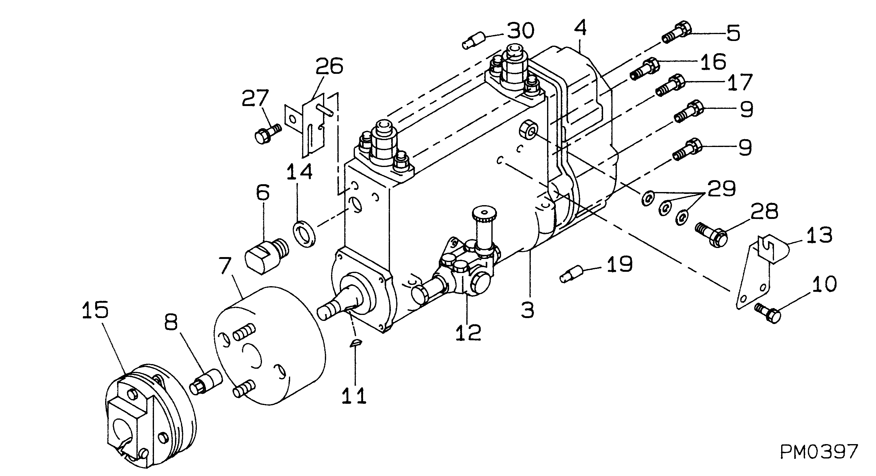
Fuel Injection Pump
Vehicle engine
TRUCK HO6CTP
Engine
HO6CTP
Serial start-end
9203-
Info
Injector Nozzle
093500-5330
Injector nozzle:
0935005330
KIT List:
Part name
Kit1
Kit2
Components :
Scheme #.#:
№
Qty
Part num
Name
Remarks
Manufacture num
000
[01]
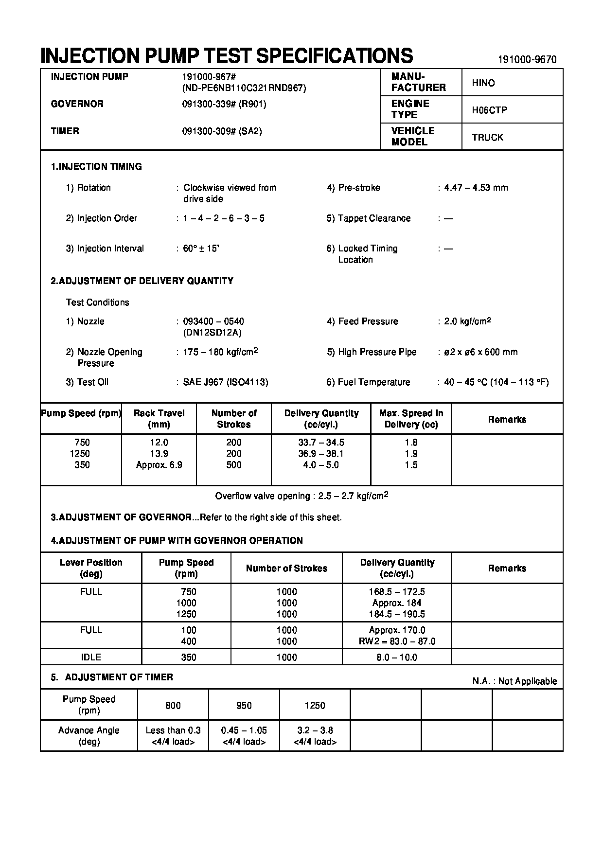
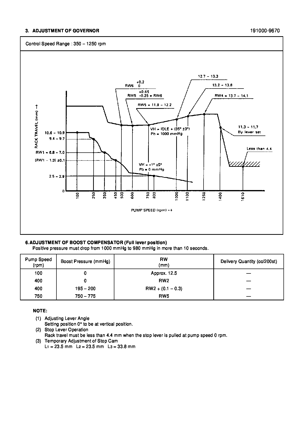
19100-09670
PUMP ASSY, INJECTI
NB6,R901
22010-6840
HINO
Include in ##:
19100-09670
as PUMP ASSY, INJECTI
Cross reference number
Part num
Firm num
Firm
Name
19100-09670
22010-6840
PUMP ASSY, INJECTI
1910009670
22010-6840
HINO
PUMP ASSY, INJECTI
Information:
Type 2 Fuel Injector. (1) Spring. (2) Rack Bar.
(3) 6V4830 Fixture Group. (4) 4C9279 Plate Assembly.Use fixture group (3) and plate assembly (4) along with the procedure in this instruction to remove and install tappet springs on injectors.Do not perform any procedure, outlined in this publication, or order any parts until you read and understand the information contained within.Removal and Installation of Fuel Injector Tappet Springs
Take care not to damage, drop, or jar the internal parts of the injector. Injector parts must be clean when reassembled. Place a light coating of clean diesel fuel, kerosene, or calibration fluid on the moving internal components during assembly.
* Clean the outside of the injector before disassembly. Install good O-ring seals on the injector and then install a 6V4172 Cleaning Sleeve. Wash the outside of the injector with solvents and a brush. Dry with pressure air.
Pressure air can cause personal injury. When using pressure air for cleaning, wear a protective face shield, protective clothing and protective shoes.The maximum air pressure must be below 205 kPa (30 psi) for cleaning purposes.
1. Remove existing plate and secure plate assembly (4) to fixture group (3).2. Remove O-ring seals from the injector prior to placing injector into fixture.3. Place injector into fixture with spring up as shown. Rack bar (2) on injector is to be extended out so that it is locked into position by two pins on plate assembly (4). 4. Using the handle of the fixture group, compress injector spring (tappet) (5) so that lock pin (6) can be pushed IN to release the tappet assembly from the injector body. 5. Remove tappet assembly from the injector body. Remove and discard old spring. Place the injector plunger on a soft clean cloth to avoid handling the plunger. Excessive handling will remove the fuel on the plunger and may result in corroding the plunger if it is left out for an extended period of time.6. Install new spring on injector body. 7. Locate the punched dot (.)(7) on the top end of the gear after it is pulled out of the body. Using a yellow magic marker, paint the whole length of the tooth that is 180° opposite the punched dot.
Injector Assembly (shown without spring).8. As the tappet/plunger assembly is inserted into the body, the yellow colored tooth on the gear should be visible in the center of the slot for the tappet lock pin.
Injector Assembly (shown without spring). 9. With the colored tooth visible in the slot of the injector body, a pin or long narrow screw driver is needed to position the gear to engage rack and pinion teeth after which the tappet assembly will drop into place.10. Using the 6V4830 Fixture Group, apply pressure on tappet (5) to compress the spring so the pin pops out and locks the tappet assembly in place.11. Remove the injector from the fixture. Push and pull the rack bar to check for smoothness in its movement. If a 6V4830 Fixture Group is not available, the 4C9279