Rating:
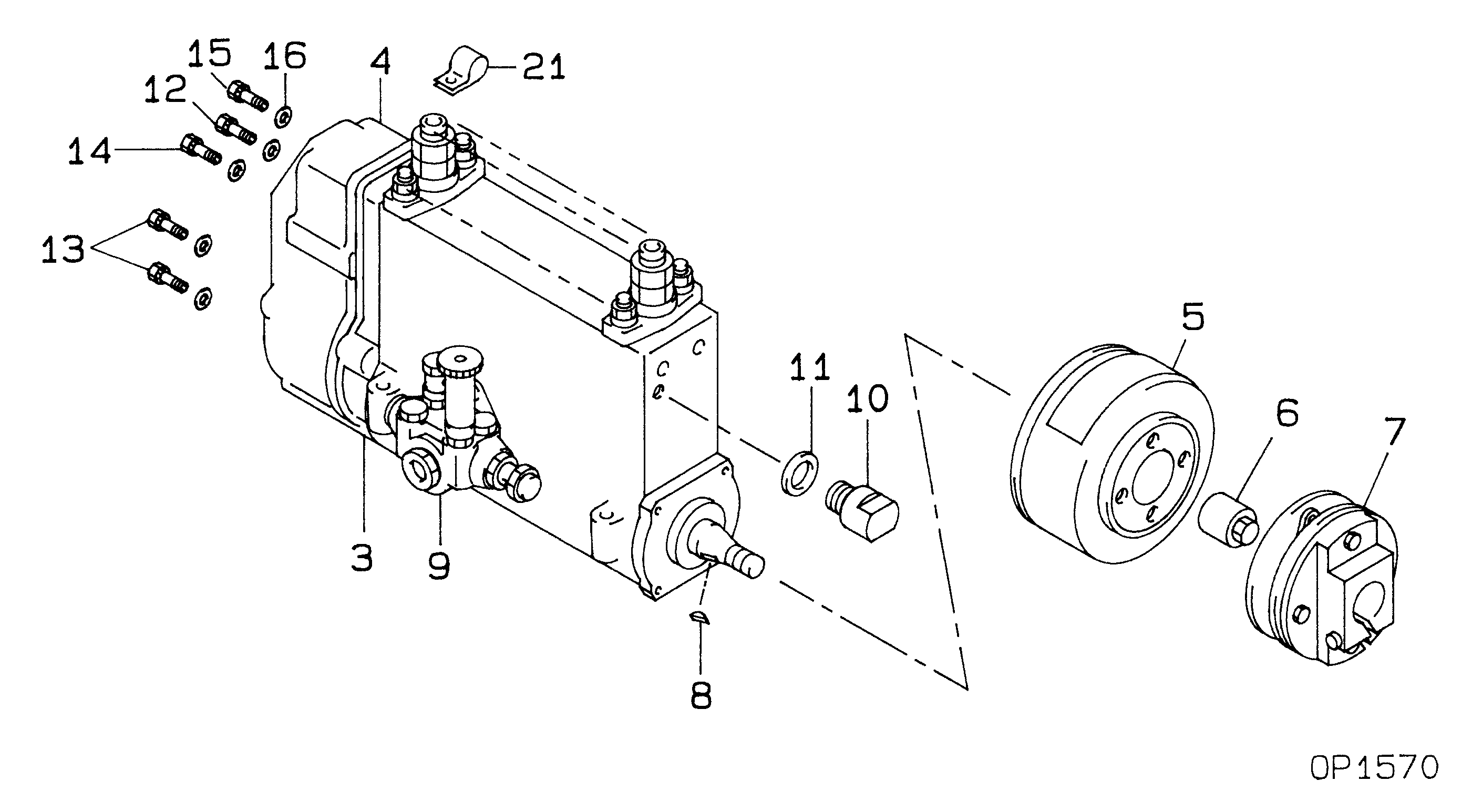
Information pump assy, injecti Denso
Components :
Scheme #.#:
№
Qty
Part num
Name
Remarks
Manufacture num
000
[01]
19100-08654
PUMP ASSY, INJECTI
NB6,R901
ME076768
MITSUBISHI
Include in ##:
19100-08654
as PUMP ASSY, INJECTI
Cross reference number
Part num
Firm num
Firm
Name
19100-08654
ME076768
PUMP ASSY, INJECTI
Information:
Specifications
Special Tools
ROCKER ARMS AND ROCKER SHAFT
Construction
Rocker System component Parts(1) Oil filler cap(2) Breather hose(3) Rocker cover(4) Rocker cover gasket(5) Rocker shaft(6) Rocker spring(7) Adjust screw(8) Rocker arm(9) Rocker stayRemoval and Installation
Caution1. Be careful not to confuse proper direction of installation of the rocker shaft.2. After installing the rocker shaft, adjust valve clearance.
Installing Rocker Shaft and Rocker CoverInspection
If any parts are found defective, replace them.
Inspecting Rocker Shaft and Rocker ArmsCYLINDER HEAD
Construction
Cylinder Head Component Parts(1) Cylinder head(2) Valve guide(3) Cylinder head bolt (Main bolt)(4) Cylinder head bolt (Sub-bolt)(5) Seat ring (3600 rpm specification engine)(6) Water outlet fitting(7) Cylinder head gasket(8) Mouth piece(9) Thermostat(10) Thermostat fittingRemoval
(1) Remove the injection pipe assembly. CAUTION* When disconnecting each injection pipe from the injection pump side delivery valve holder, grasp the holder with a wrench to prevent it from loosening.* After removing the pipe assembly, plug the nozzle holders and delivery valve holders to prevent intrusion of dust.(2) Disconnect the glow plug lead wire.(3) Loosen the alternator bracket bolts and dismount the alternator.(4) Disconnect the air breather hose.(5) Remove the rocker cover.(6) Remove the rocker shaft assembly.(7) Loosen the cylinder head mounting bolts in the numerical order illustrated at right and remove the cylinder head assembly (including the intake and exhaust manifold).(8) Remove the cylinder head gasket.Clean the cylinder head and the cylinder block surface from which the gasket has been removed.(9) Remove the nozzle holder assemblies and glow plugs from the cylinder head.(10) Remove the intake manifold and exhaust manifold from the cylinder head.(11) Remove the valve retainers, valve springs, and valves from the cylinder head. CAUTION* When removing each valve retainer, depress the retainer against the valve spring and remove the retainer lock. Identify each valve by putting a mark indicating the number of cylinder from which the valve is removed.(12) Remove the valve stem seals.
Sequence for Loosening Cylinder Head Bolts (L2)
Sequence for Loosening Cylinder Head Bolts (L3)
Removing ValvesInspection and Repair
Inspection of Cylinder HeadReplacement of Valve Guide
If a valve guide is found defective, replace it.1. RemovalPress the guide at its upper end and pull it out to the valve seat side.2. Installation (Press-fitting)Press-fit the guide from the upper side of the cylinder head to a height of 14 0.5 mm from the valve spring seat face.
Press-fitting Valve GuideRepair of Valve Seat
If a valve seat is found defective, reface it or replace the cylinder head. CAUTION* When checking valve sinkage, the valve guide must be in the normal condition.* Resurface the valve seat so that it contacts the mid-portion of the valve face.
Checking Valve Sinkage
Resurfacing Valve Seat (Common to intake and exhaust valves)Installation
Installation of the cylinder head is in the reverse order of removal. Pay attention to the following:(1) Renew the cylinder head gasket. No application of sealant is necessary. On the upper front of the gasket is engine model to which that gasket is applicable. Be careful not to confuse with a gasket for other engine model.(2) Tighten the cylinder head bolts in the numerical order shown in the figure at right,