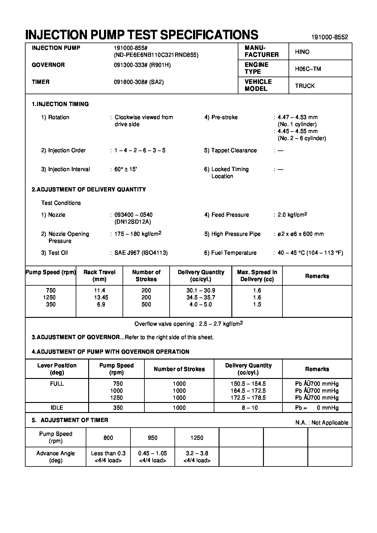
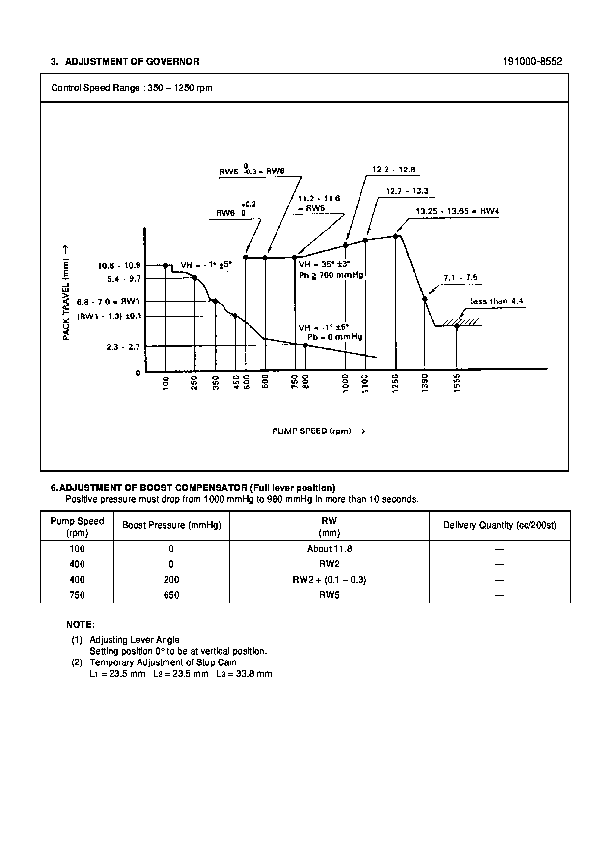
Rating:
Information pump assy, injecti Denso
Components :
Scheme #.#:
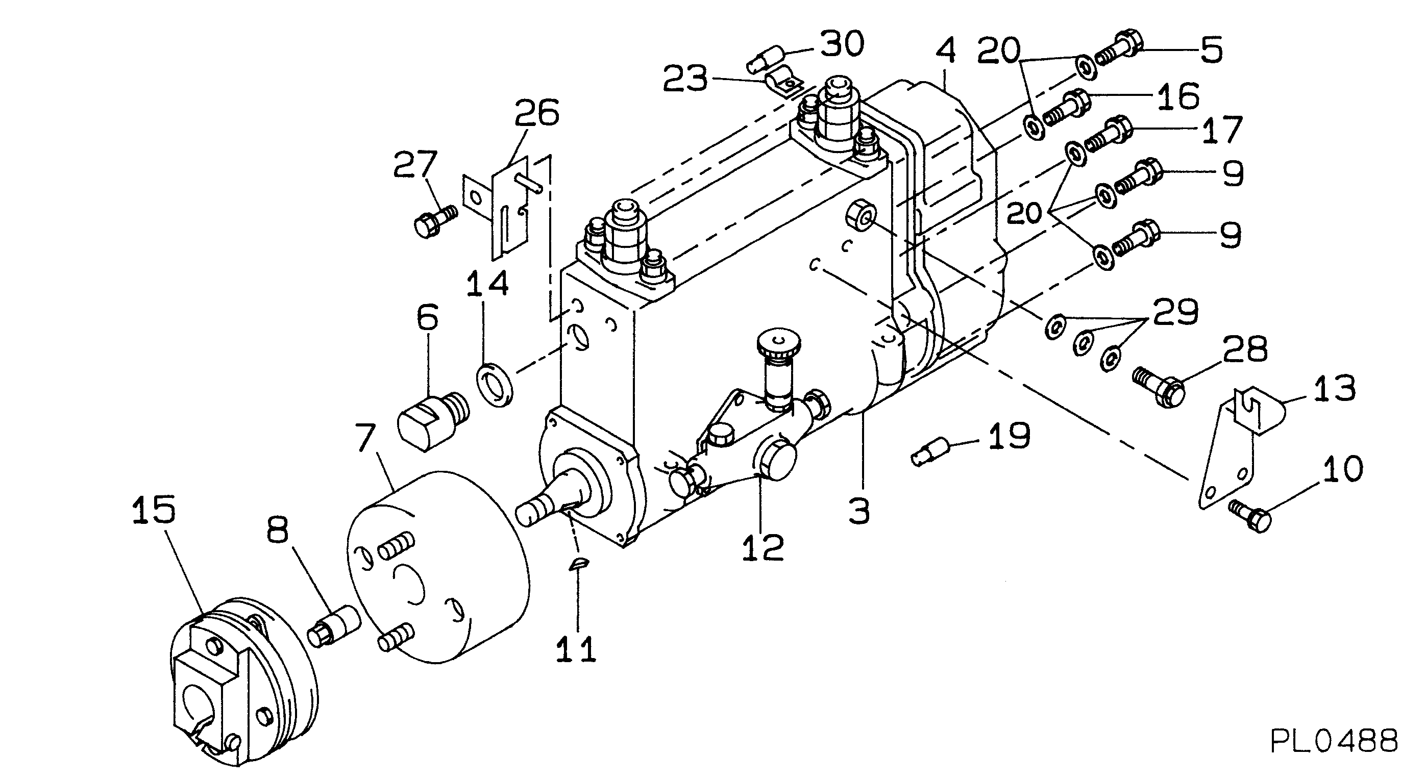
№
Qty
Part num
Name
Remarks
Manufacture num
000
[01]
19100-08552
PUMP ASSY, INJECTI
NB6R901H
22010-6333
HINO
Include in ##:
19100-08552
as PUMP ASSY, INJECTI
Cross reference number
Part num
Firm num
Firm
Name
19100-08552
22010-6333
PUMP ASSY, INJECTI
Information:
Installation of Tappets
(1) Apply engine oil to the outside surfaces of tappets, and insert them into the tappet bores in the crankcase. (2) Make sure the tappets rotate smoothly.
Installation of tappetInstallation of Main Bearings
(1) Install the main bearings (upper and lower halves) to the crankcase and main bearing caps by inserting them into the lug grooves. Install the bearings with lug groove to the crankcase, and the bearings without lug groove to the main bearing caps.(2) Install the flanged bearing to the aftermost (No. 4) journal.(3) Apply a small amount of engine oil to the inside surface of each bearing.
Installation of main bearingInstallation of Crankshaft
(1) Wash the crankshaft thoroughly with a cleaning solution, and dry it with compressed air. After washing the crankshaft, make sure there is no metal particles inside the oil holes or swelling of the chamfered sections of the oil holes.(2) Hold the crankshaft horizontally, and carefully place it into the crankcase.(3) Apply a small amount of engine oil to the crankshaft journals.
Installation of crankshaftInstallation of Main Bearing Caps
Fit the main bearings, making sure that the front marks (arrow) on the main bearing caps face the front of the engine and the cap numbers are in order from the front to the back.
Make sure the end faces of the bearing caps No.1, 4 are flush with the crankcase end faces.
Installation of main bearing capTightening of Bearing Cap Bolts
Tighten the main bearing cap bolts alternately to the specified torque.
Installation of main bearing cap boltInspection of Crankshaft for Smooth Rotation
Make sure that the crankshaft rotates smoothly
Inspection of crankshaft for smooth rotationMeasurement of Crankshaft End Play
(1) Measure the crankshaft end play. (2) If the end play is too small, loosen the cap bolts, and retighten them.(3) If the limit value is exceeded, replaced the flanged bearing.
Measurement of crankshaft end playAssembly of Pistons and Connecting Rods
(1) Assemble the piston and connecting rod by positioning the piston weight indication and the connecting rod matching mark face the same direction.(2) Coat the piston pin with engine oil, and install the pin to connect the connecting rod to the piston.
Assembly of piston and connecting rod (1)(3) Install the snap rings in the grooves in the piston using ring pliers. Check the snap rings for tension and proper fitting. The snap ring ends must be positioned toward the bottom of the piston.
Assembly of piston and connecting rod (2)Installation of Piston Rings
(1) Using piston ring pliers, install the compression rings (No. 1, No. 2) and oil ring on the piston. The marks on rings No. 1 and No. 2 (No. 1: RN, No. 2: R) must be positioned toward the top of the piston.
Installation of piston rings on piston(2) Install the oil ring in such a way that its ring end cap is positioned 180° from the joint of the oil spring.
Positioning of oil ring and coil springLaying Crankcase on its Side
Gently lay the crankcase on its side.
Laying of crankcase on its sidePreparation for Piston Installation
After cleaning the inside surface of the cylinder with