Rating:
Information pump assy, injecti Denso
Product
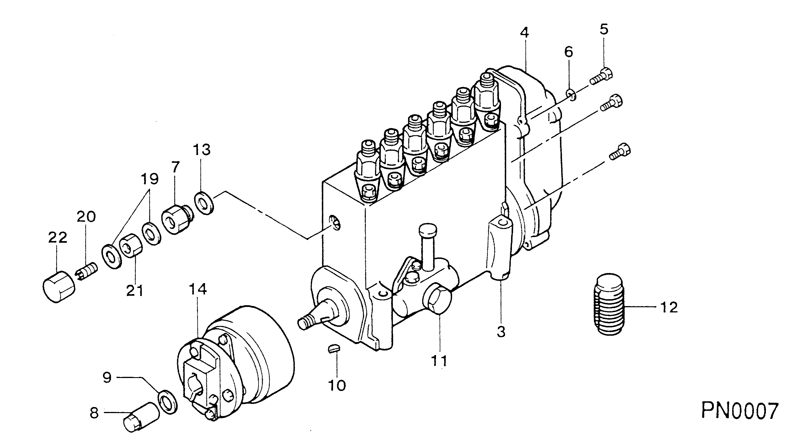
Fuel Injection Pump
Vehicle engine
Construction machine SA6D140
Engine
SA6D140
Serial start-end
8911-
Info
Injector Nozzle
093500-3080
KOMATSU
PUMP ASSY, INJECTI
LA
- *1 THE ELEMENT HAS BEEN CHANGED.
Injector nozzle:
0935003080
KIT List:
Part name
Kit1
Kit2
Components :
Scheme #.#:
№
Qty
Part num
Name
Remarks
Manufacture num
000
[01]
19100-07720
PUMP ASSY, INJECTI
NE6,RSUV
-9201
Include in ##:
19100-07720
as PUMP ASSY, INJECTI
Cross reference number
Part num
Firm num
Firm
Name
19100-07720
KOMATSU
PUMP ASSY, INJECTI
Information:
Delco-Remy Starting Motor
Fig. 1-Delco-Remy Starting MotorRemoval
Starter is located on either right or left side of engine at the rear.Disconnect battery negative (-) cable.Disconnect wires from starting motor.Remove cap screws that attach motor to flywheel housing. The JDE-80 starter wrench may be necessary to remove the rear attaching cap screw.Testing And Diagnosis
Solenoid Tests (Starting Motor Removed)
Fig. 2-Solenoid Pull-In Test Testing Pull-In WindingsDisconnect field connector from solenoid motor terminal. Connect ammeter in series with a carbon pile resistor to terminal "S" and to battery. Connect voltmeter (1) to terminal "S" and to solenoid motor terminal (Fig. 2). With carbon pile (2) in the off position, connect other battery post (3) to solenoid motor terminal. Quickly adjust the carbon pile (2) to obtain 5 volts. The ammeter (4) reading should be 13 to 15.5 amps. Testing Hold-In WindingsDisconnect solenoid. Connect ammeter in series with a switch to terminal "S" and to battery. Connect voltmeter to terminal "S" and to solenoid ground. Connect carbon pile resistor across the battery. Connect other battery post to solenoid ground. Close the switch and adjust carbon pile to obtain 10 volts. The ammeter reading should be 14.5 to 16.5 amps. High Ammeter ReadingWindings are grounded or short circuited Low Ammeter ReadingExcessive resistance is present (usually in a connection) No Ammeter ReadingWindings are open circuitedTo prevent overheating, do not energize the pull-in winding longer than 15 seconds. Current draw will decrease as the winding temperature increases.If the fault cannot be repaired and the solenoid performance is questionable, replace the windings.No Load Starting Motor Test (Fig. 3)
Fig. 3-No Load Starter Test CircuitPlace starter in a vise.Connect the circuit in Fig. 3 starting with the battery positive terminal (2) with heavy wire to the ammeter (3) then to the "BAT." contact of the solenoid. Connect a switch across the "BAT." and S of the solenoid.Place a voltmeter from the M terminal to the starter motor casing. Connect the starter motor casing to the negative of the battery. Connect a carbon pile to the positive and negative of the battery to adjust the voltage. Connect a tachometer to the starter motor.
Fig. 4-Test Data For A Delco-Remy StarterThe meters should read as follows (Fig. 4).Interpret the test results as follows:1. Rated current draw and no load speed indicates normal condition of the starting motor.2. Low free speed and high current draw indicates: a. Too much friction - tight, dirty, or worn bearings, bent armature shaft or loose pole shoes, allowing armature to drag.b. Shorted armature. This can be further checked on a growler after disassembly.c. Grounded armature or fields. Check further after disassembly.3. Failure to operate with high current draw indicates: a. A direct ground in the terminal or fields.b. Frozen bearings (this should have been determined by turning the armature by hand).4. Failure to operate with no current draw indicates: a. Open field circuit. This can be checked after disassembly by inspecting internal conditions and tracing circuit with a test lamp.b. Open armature coils. Inspect the commutator for badly burned