Rating:
Information pump assy, injecti Denso
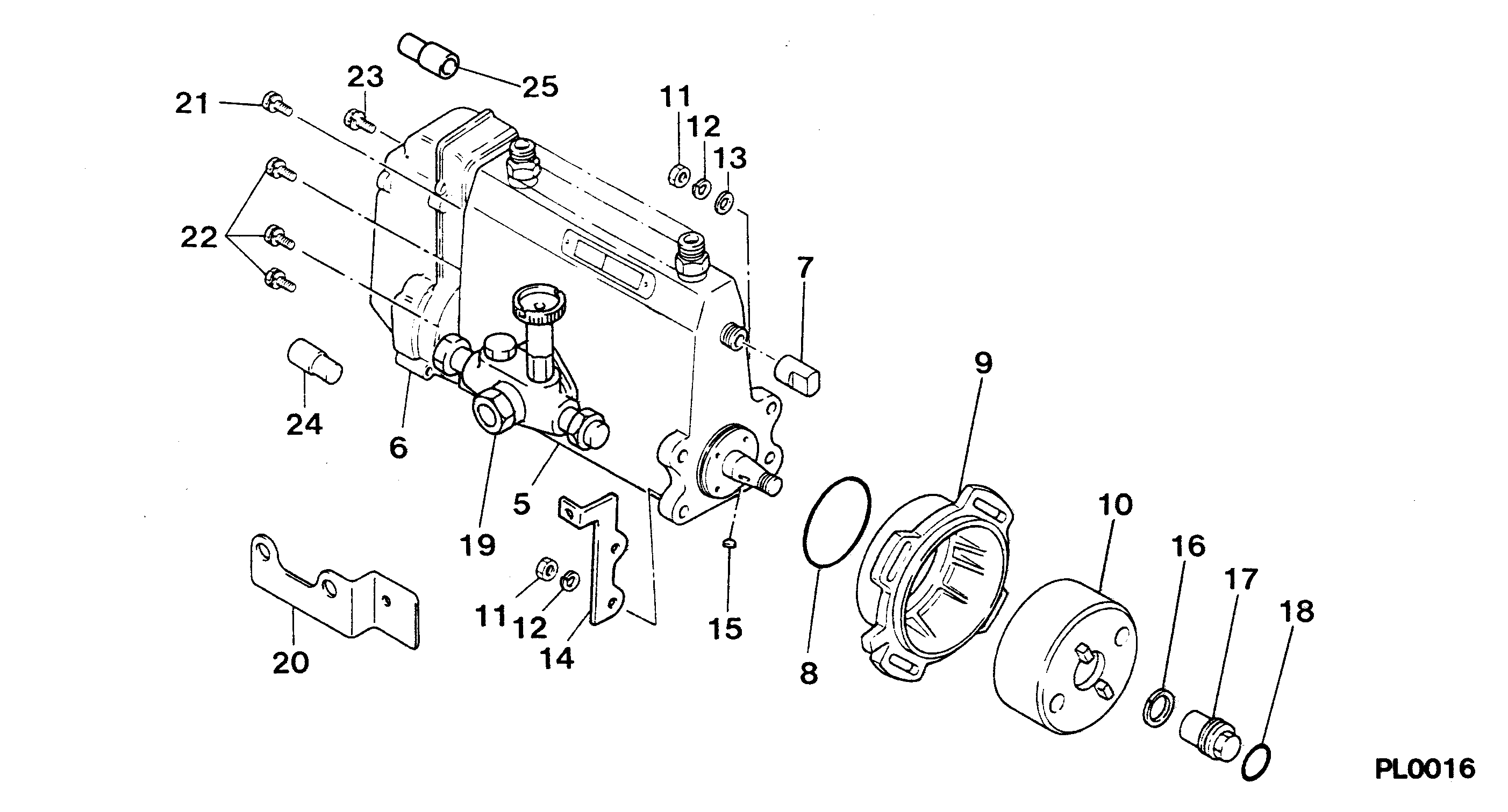
Components :
Scheme #.#:
№
Qty
Part num
Name
Remarks
Manufacture num
000
[01]
19100-07552
PUMP ASSY, INJECTI
A6,R801
ME076571
MITSUBISHI
Include in ##:
19100-07552
as PUMP ASSY, INJECTI
Cross reference number
Part num
Firm num
Firm
Name
19100-07552
ME076571
PUMP ASSY, INJECTI
Test Calibration Data:
1910007550
ME076571
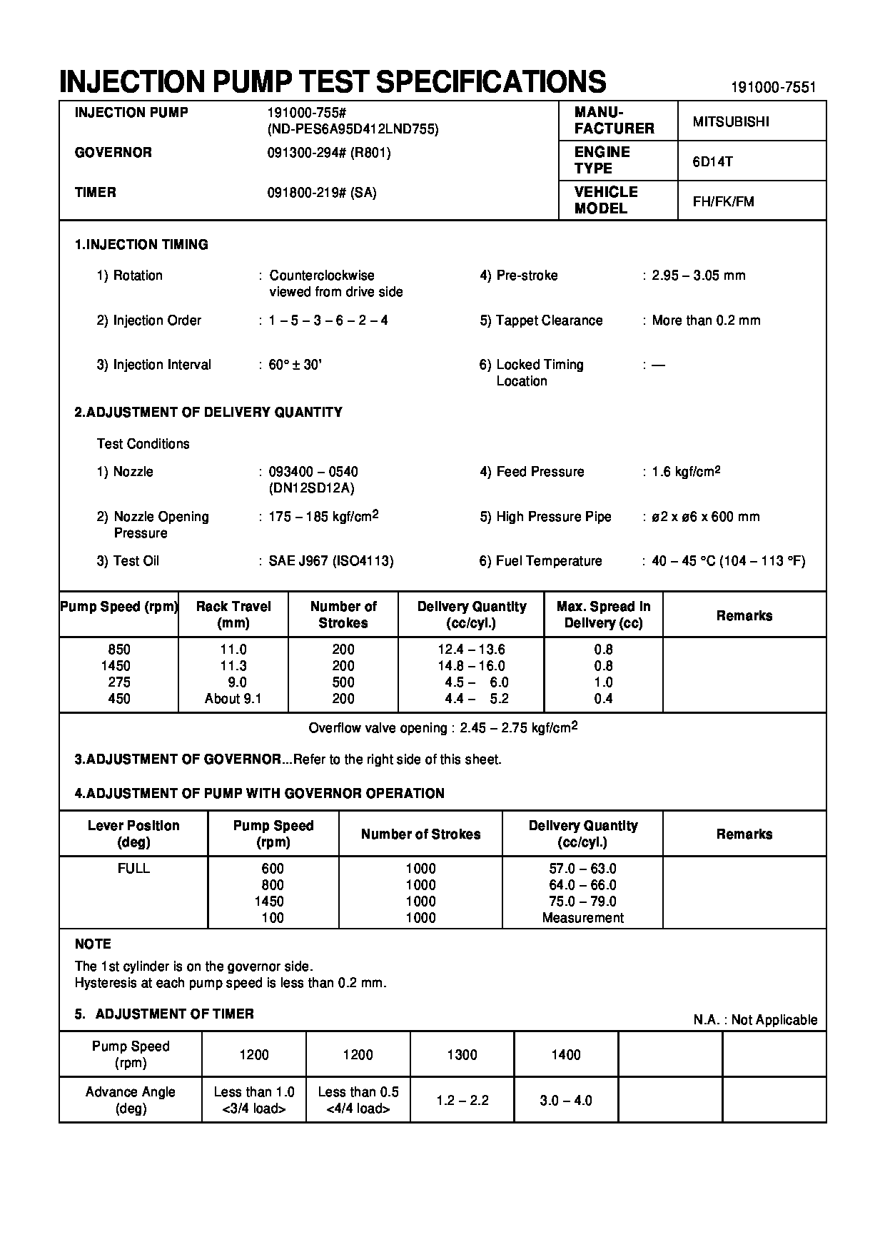
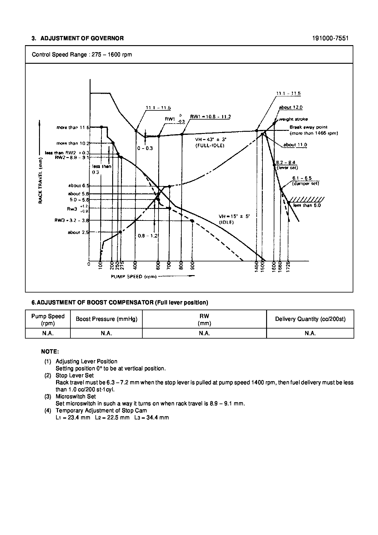
1910007551
ME076571
Information:
Removal
Fig. 1-Oil Cooler LinesDisconnect coolant lines (1, Fig. 1).Remove oil filter (2).
Fig. 2-Oil Cooler NippleUnscrew oil cooler nipple (Fig. 2) and lift oil cooler off of cylinder block.Remove four sided packing from bottom of oil cooler.Repair
Pressure check the coolant side of the oil cooler using 15 psi (103 kPa) (1 bar) maximum air pressure.Remove oil cooler bypass valve by driving it out the bottom of the oil cooler from the top side.
Fig. 3-Oil Cooler Bypass Valve and SpringInspect bypass valve and spring (Fig. 3) for damage and replace as necessary.Installation
Fig. 4-Four Sided PackingInstall new four sided packing (Fig. 4) on bottom of oil cooler.Position oil cooler on engine and install oil cooler nipple.
Fig. 5-Oil Cooler NippleOil cooler nipple torque (Fig. 5) ... 20 to 25 lb-ft(27 to 34 N m) (3.0 to 3.5 kg-m)Connect coolant hoses to oil cooler and install new oil filter (Group 0407).4-276D, 4-276T, 6-414D Or 6414T Engine
Removal
Fig. 6-Oil Cooler Assembly RemovalDisconnect coolant lines (1, Fig. 6) and remove oil filter (2).Remove oil cooler assembly attaching cap screws (3).Remove oil filter housing (4) from oil cooler.Repair
Remove top and bottom covers.
Fig. 7-Remove Oil CoolerUsing a suitable driver, drive oil cooler out of housing from bottom side (Fig. 7).
Fig. 8-Remove Oil Cooler Relief ValveDrive oil cooler bypass valve out the bottom from the top using a pin punch against the top of the valve (Fig. 8).
Fig. 9-Oil CoolerInspect oil cooler for damage or build-up of foreign material and clean as needed.The oil cooler can be pressure checked with a maximum of 50 psi (345 kPa) (3 bar) air pressure.
Fig. 10-Oil Cooler Bypass Valve Spring LengthCheck oil cooler bypass valve spring length:Valve spring length (Fig. 10) ... 1.91 inch(48.5 mm)when compressed with ... 29.5 to 37.5 lb(131 to 167 N)
Fig. 11-Remove O-RingsRemove O-rings from housing at bottom of oil cooler bore.Remove all gasket residue from parts.Installation
Fig. 12-Install Oil Cooler Relief ValvePosition oil cooler relief valve spring (1, Fig. 12), valve (2), and valve seat (3) in bore in bottom of housing (4).
Fig. 13-Drive Oil Cooler Relief Valve SeatUsing a suitable driver (Fig. 13), drive the valve seat into the housing until the seat bottoms.
Fig. 14-O-Ring InstallationInstall new O-rings in housing at bottom of oil cooler bore, black O-ring in upper groove (A, Fig. 14) and red O-ring in lower groove (B).Using new gasket, install oil cooler in housing from top side, being careful not to shear O-rings.Using new gaskets, install top and bottom covers and oil filter housing.Position oil cooler assembly on engine and install cap screws.Connect oil cooler coolant lines and install a new oil filter.