Rating:
Information pump assy, injecti Denso
Product
Fuel Injection Pump
Vehicle engine
MARINE SA6D117
Engine
SA6D117
Serial start-end
8904-
Info
Injector Nozzle
093500-3630
Injector nozzle:
0935003630
KIT List:
Part name
Kit1
Kit2
Components :
Scheme #.#:
№
Qty
Part num
Name
Remarks
Manufacture num
Cross reference number
Part num
Firm num
Firm
Name
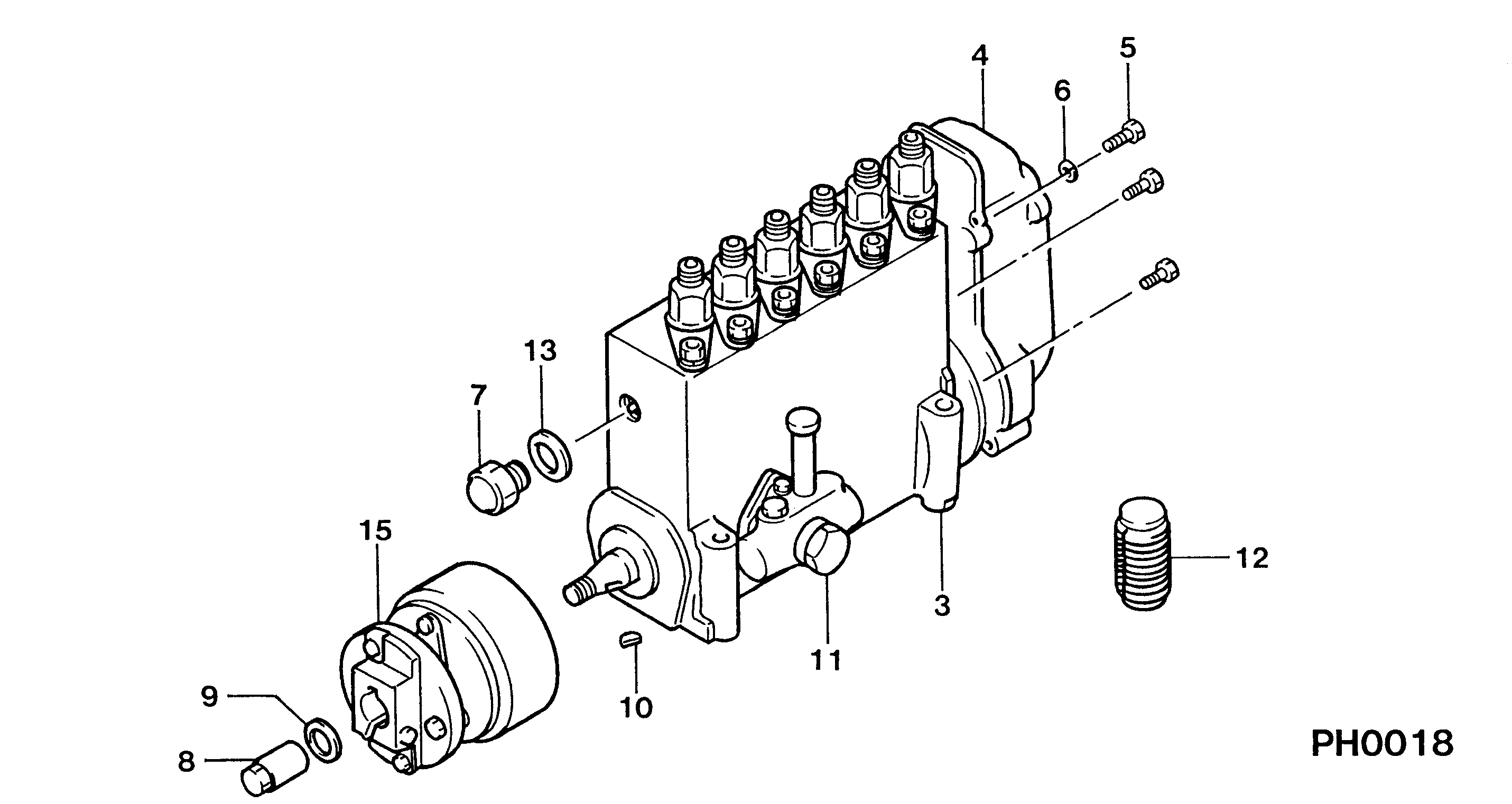
19100-07450
PUMP ASSY, INJECTI

Information:
Typical Example1. With the rear of wire connector toward you, snap tool (A) (the correct size for the wire being removed) over the wire of the contact to be removed.2. Slide tool (A) along the wire into the contact cavity until it engages the contact and resistance is felt. Do not twist or insert tool (A) at an angle.
Typical Example3. Pull contact (2) and wire assembly out of connector (1).4. Remove the damaged contact from the wire.
Typical Example5. Use tool (B) and the following procedure to secure contact (2) to the wire.a. Strip 6.3 mm (.25 in.) insulation from the wire.b. Raise selector knob (3) and rotate until arrow is aligned with the wire size to be crimped.c. Loosen locknut. Turn adjusting screw (4) in (clockwise) until it stops.
Typical Exampled. Insert contact (2) into tool (B). Turn the adjusting screw out (counter clockwise) until the contact is flush with indentor cover (5) on tool (B). Tighten locknut.
Typical Examplec. Insert wire in contact (2). The contact must be centered between the indentors. Close the handles until the handle contacts the stop.d. Release the handles and remove the crimped contact.e. Inspect the contact to insure that all wire strands are inside the crimp barrel. Look in the hole in the contact. If the crimp is correct wire strands will be visable in the hole in the contact.
Typical Example6. Grasp the wire approximately 25.4 mm (1.00 in.) behind the contact crimp barrel.7. Hold connector (1) with the rear grommet facing you.8. Push contact (2) straight into connector (1) until a positive stop is felt.9. Gently pull on the wire and connector assembly to confirm that the contact is properly locked in place.