Rating:
Information pump assy, injecti Denso
Product
Fuel Injection Pump
Vehicle engine
INDUSTRIAL 6D14C
Engine
6D14C
Serial start-end
8804--8805
Info
Injector Nozzle
093500-2070
Injector nozzle:
0935002070
KIT List:
Part name
Kit1
Kit2
Components :
Scheme #.#:
№
Qty
Part num
Name
Remarks
Manufacture num
000
[01]
19100-06170
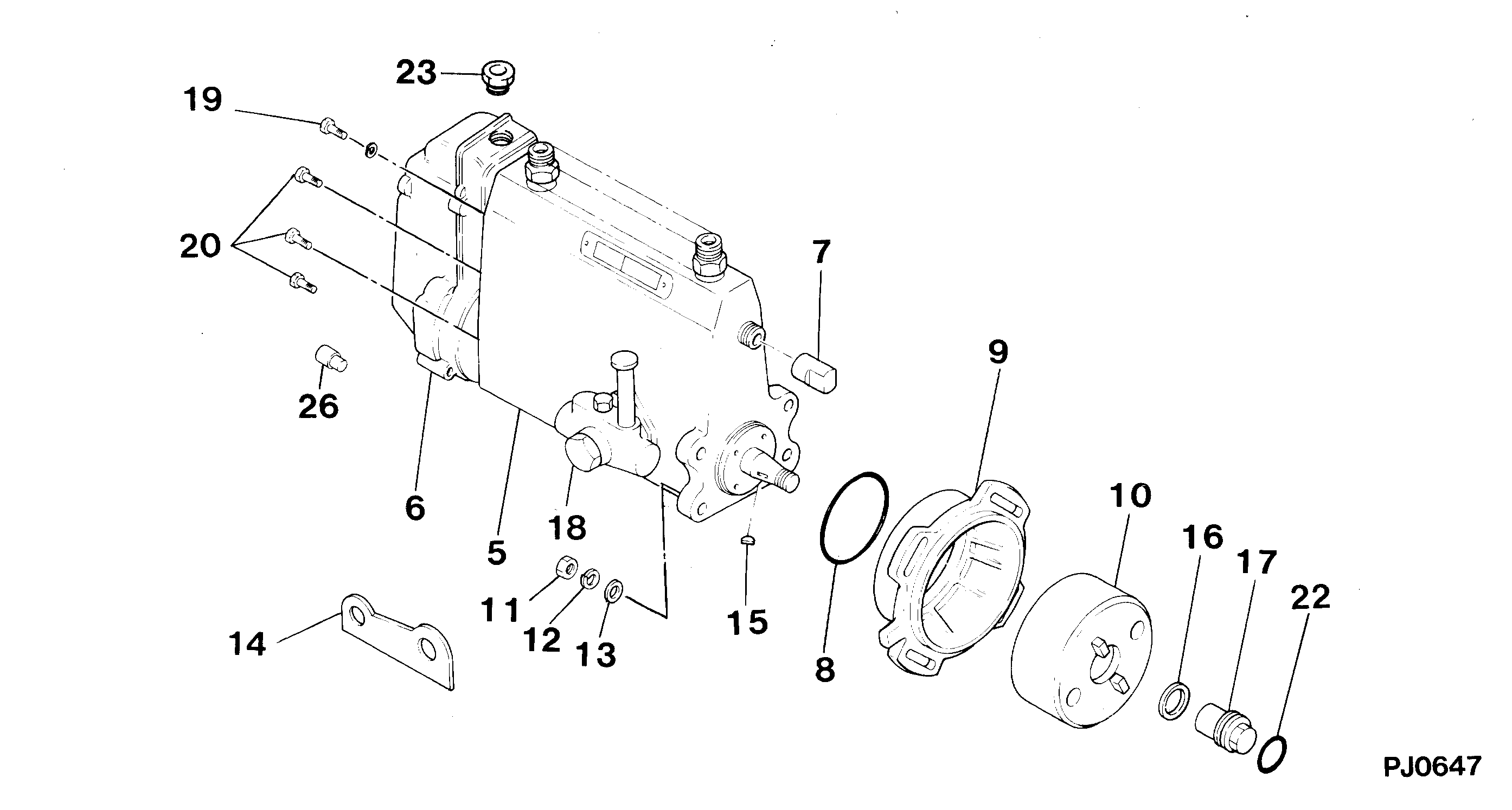
PUMP ASSY, INJECTI
A6,RSV
Include in ##:
19100-06170
as PUMP ASSY, INJECTI
Cross reference number
Part num
Firm num
Firm
Name
19100-06170
PUMP ASSY, INJECTI
Information:
Improper operation, lubrication, maintenance, or repair of this product can be dangerous and could result in injury or death. Do not operate or perform any lubrication, maintenance, or repair on this product until you have read and understood the operation, lubrication, maintenance, and repair information.Hot oil and components can cause personal injury. Do not allow hot oil or components to contact skin.Always use a board or cardboard when checking for a leak. Escaping fluid under pressure, even a pin-hole size leak, can penetrate body tissue, causing serious injury, and possibly death. If fluid is injected into the skin, it must be surgically removed within a few hours by a doctor familiar with this type of injury.
Operations that may cause product damage are identified by notice labels in this publication.
Introduction
This Tool Operating Manual contains two filter installation procedures. This first procedure is for installing a primary filter system. This is a coarse filter and will protect the transfer pump from contamination in the oil. The second procedure outlines installing a secondary filter which is designed to protect injection pumps from contaminated oil. Fuel injection pumps used on the 3208 Engine are one example of a fuel injection pump that requires the secondary filter installation.It will be the dealer choice as to which optional filter is installed on the test stand. Determine what type of filtering will be required most often, and install the appropriate type of filtering system. These filters can only be added to the 15 horsepower test stands.Secondary Filter
Nomenclature
Illustration 1. Nomenclature for Secondary Filter Installation. Refer to Chart A for item identification. Fabricated Parts
All the parts required for this installation can be ordered from Caterpillar Parts Distribution, except bracket (1). This must be manufactured by the bench owner, using the dimensions provided below.This bracket can be made from common SAE1018 steel. Weld the two pieces together.
Illustration 2. Filter Mounting Bracket. Refer to Chart B for dimensions. Installation
Assemble the Fuel Filter
1. Install 053-0088 Fitting (17) with 3J-1907 Seal (18) into the inlet port (left side) of the filter base. (This converts a number 6 STOP port to NPT). Install 5P-4455 Fitting (19) into fitting (17).2. Install 2R-6806 Fitting (15) with 3J-1907 Seal (16) into the outlet port (right side) of the filter base.3. Install 6N-4414 Cover (7) onto the filter base using 1P-0436 Gasket (8), 4B-3388/6V-2317 (9), and OS-1616/6V-8490 Bolt (10).4. Install 9S-4182 Plug (5) with 6V-5084 O-ring Seal (6) into the top of the filter base.5. Install the filter base assembly onto filter bracket (1), as shown in Illustration 1, using the two OS-0509 Bolts (4).Mount the Fuel Filter Assembly to the Test Stand
Mount the suction supply filter group and bracket assembly between the cooling fan and the fuel filter group, as shown in Illustration 1.1. Remove the two lower left-side panels from the test stand to access the calibration fluid tank, and the controls and connections area under the test stand.
Illustration 3. Remove Plug From Under Connector (22).2. Remove plug from the underside of connector