Rating:
Information pump assy, injecti Denso
Product
Fuel Injection Pump
Vehicle engine
TRUCK EH700
Engine
EH700
Serial start-end
8803-
Info
Injector Nozzle
093500-2080
Injector nozzle:
0935002080
KIT List:
Part name
Kit1
Kit2
Components :
Scheme #.#:
№
Qty
Part num
Name
Remarks
Manufacture num
000
[01]
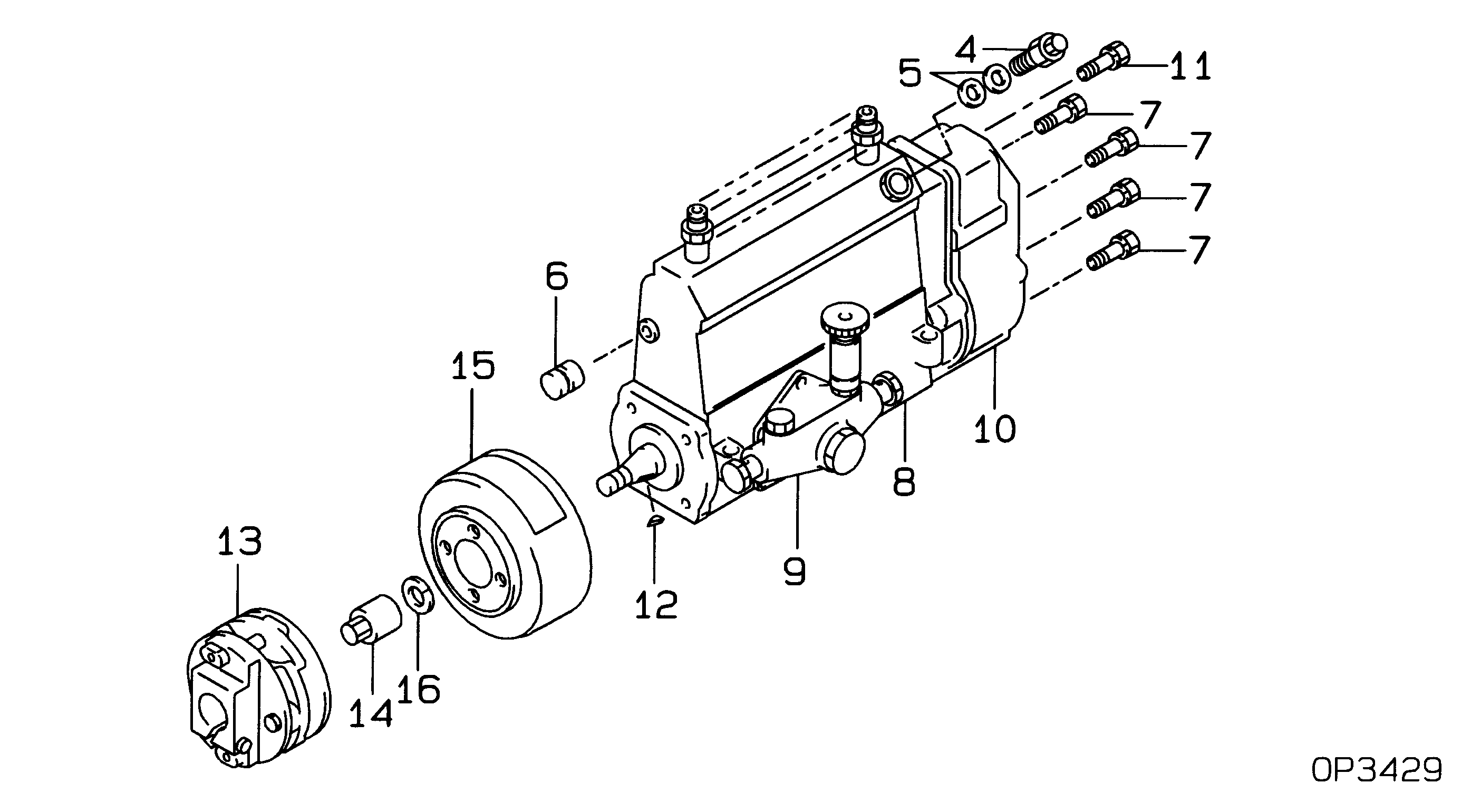
19100-05820
PUMP ASSY, INJECTI
A6,R812
22090-1540
HINO
Include in ##:
19100-05820
as PUMP ASSY, INJECTI
Cross reference number
Part num
Firm num
Firm
Name
19100-05820
22090-1540
PUMP ASSY, INJECTI
1910005820
22090-1540
HINO
PUMP ASSY, INJECTI
Information:
Dismantling:
1. Remove the belt driving the air compressor and dismantle the second vee-belt pulley on the crankshaft.
5-32. Remove belt driving generator and cooling air blower, and secure vee-belt pulley of crankshaft, using retainer No. 143400 and remove the stud securing the vee-belt pulley and dismantle the vee-belt pulley.Fig. 5-3 The stud securing the vee-belt pulley has a left-hand thread.Installing:
5-41. Align the locating hole in the vee-belt pulley with the locating pin in the crankshaft gearwheel and slide the vee-belt pulley into position.Fig. 5-4
5-52. Having ascertained that the vee-belt pulley is correctly located, tighten and lock down the stud (which has a lefthand thread) in accordance with the instructions for tightening studs and bolts. (Use retainer No. 143400 and angle-of-turn indicator No. 101910).Fig. 5-5
5-63. Mount the pulley to drive the air compressor on the main vee-belt pulley.Fig. 5-64. Assemble the nuts. Mount and tension the vee belts for driving the blower, generator and air compressor.Removing And Refitting Front Radial Sealing Ring For Crankshaft
Removal:
5-7Apply puller No. 142700 and draw off radial sealing ring.Fig. 5-7Refitting:
1. Grease slightly sealing lip of new radial sealing ring.
5-82. Fit radial sealing ring in such a way that lip shows inwards. Press on ring with fitting device.Fig. 5-8 Pay attention to contact traces of radial sealing ring. See also Fig. 5-31. If the contact surface shows on the crankshaft a friction groove caused by the radial ring, displace the latter axially in the front cover.
5-9 When moving radial seal, observe correct depth of installation (pressed in). Depth 1 see Fig. 5-9, outside flush with front-end cover.
5-10Depth 2 (after shifting in front-end cover to be flush inside) : max. 1.0 mm.Fig. 5-10Dismantling And Installing The Vee-Belt Tensioner (As from 3 cylinder engine)
Dismantling:
1. Dismantle the holder for the warning system operator. Remove the vee belt driving the cooling air blower.2. Dismantle the vee-belt tensioner. Remove the rubber O-seal on the vee-belt tensioner.Installing:
5-111. Fit a new rubber O-seal on the vee-belt tensioner.Fig. 5-11
5-122. Mount the vee-belt tensioner with the idler pulley facing outwards.Fig. 5-12
5-133. Mount the holder of the warning system operator if the engine is equipped with an alarm system for breakage of the blower belt. Fit a spacer sleeve between the holder and front cover.Fig. 5-13
5-144. Check the alignment of the vee belt running from the idler pulley to the belt pulley mounted on the crankshaft.Fig. 5-145. If misalignment has to be corrected dismantle the vee-belt idler pulley.Checking And Repairing The Vee-Belt Tensioner
Tensioner is removed.
5-151. If the idler is damaged or its bearing worn, dismantle it from the tensioning lever. Check the radial clearance of the shaft of the vee-belt tensioner.Fig. 5-152. If the shaft has too much radial clearance or if the torsion spring is weak or broken, dismantle the vee-belt tensioner.
5-163. After prising out the shaft seal, press out the bearing bushings that are to be renewed. Press in new bearing bushing flush on the inside. Before pressing in the outer bearing bushing, measure the height of the shaft seal and then press in the