Rating:
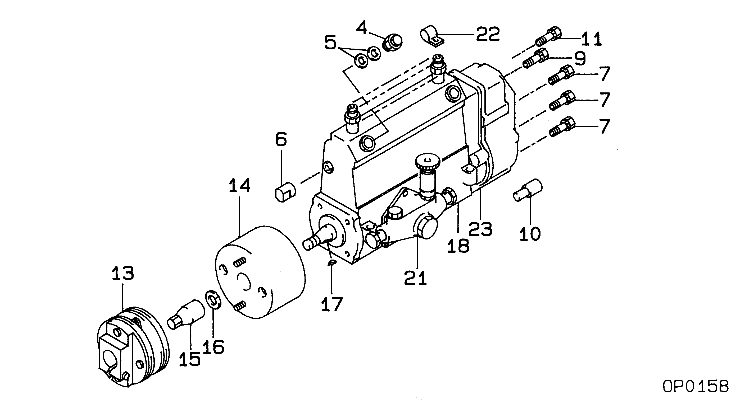
Information pump assy, injecti Denso
Components :
Scheme #.#:
№
Qty
Part num
Name
Remarks
Manufacture num
000
[01]
19100-05022
PUMP ASSY, INJECTI
NF6,R801
22010-5272
HINO
Include in ##:
19100-05022
as PUMP ASSY, INJECTI
Cross reference number
Part num
Firm num
Firm
Name
19100-05022
22010-5272
PUMP ASSY, INJECTI
Information:
Introduction
Do not perform any procedure in this Special Instruction until you have read the information and you understand the information. Caterpillar recommends that this repair is made off engine, but the repair can be performed on engine if the proper precautions are followed. This repair is to be performed before the Diesel Oxidation Catalyst (DOC) cracks.References
Reference: Special Instruction, REHS1841, "General Welding Procedures"Reference: Operation and Maintenance Manual, M0103079, "Welding on Engines with Electronic Controls"Safety Section
Do not operate or work on this product unless you have read and understood the instruction and warnings in the relevant Operation and Maintenance Manuals and relevant service literature. Failure to follow the instructions or heed the warnings could result in injury or death. Proper care is your responsibility.
Failure to follow all safety guidelines prescribed in this document and by governing authorities and regulatory agencies may result in severe injury or death of personnel or machine damage.
Observe the safe working load limits of all lifting and blocking devices and keep a safe distance from suspended/blocked loads. Personnel may be seriously injured or killed by falling loads.
Personal injury or death can result from fumes, gases and ultraviolet rays from the weld arc.Welding can cause fumes, burn skin and produce ultraviolet rays.Keep your head out of the fumes. Use ventilation, exhaust at the arc, or both, to keep fumes and gases from your breathing area. Wear eye, ear and body protection before working.Protect yourself and others; read and understand this warning. Fumes and gases can be dangerous to your health. Ultraviolet rays from the weld arc can injure eyes and burn skin. Electric shock can cause death.Read and understand the manufacturer's instructions and your employer's safety practices. Do not touch live electrical parts.See "American National Standard Z49.1, Safety in Welding and Cutting" published by the American Welding Society.American Welding Society
2501 N.W. 7th Street
Miami, Florida 33125
See "OSHA Safety and Health Standards, 29 CFR 1910", available from U.S. Department of Labor.U.S. Department of Labor
Washington, D.C. 20210
Do not ground the welder to electrical components such as the ECM or sensors. Improper grounding can cause damage to the drive train, the bearings, hydraulic components, electrical components, and other components.Do not ground the welder across the centerline of the package. Improper grounding could cause damage to the bearings, the crankshaft, the rotor shaft, and other components.Clamp the ground cable from the welder to the component that will be welded. Place the clamp as close as possible to the weld. This will help reduce the possibility of damage.
Required Parts
Table 1
Required Parts
Qty Part Number Part Name
2 303-1968(1) Gasket
4 346-0335(1) Band Clamp
4 536-5400 Plate
(1) If the DOCs are removed during welding, use the 303-1968 Gaskets and 346-0335 Band Clamps during installation.Rework Procedure
Illustration 1 g06519261
Illustration 2 g06519266
Record the serial number and part number from the back side of the DOC.Note: Perform the welding in areas that are free from explosive hazards.
Stop the engine. Turn the switched power to the OFF position.
Disconnect the negative battery cable from the battery. If a battery disconnect switch is provided, turn