Rating:
Information pump assy, injecti Denso
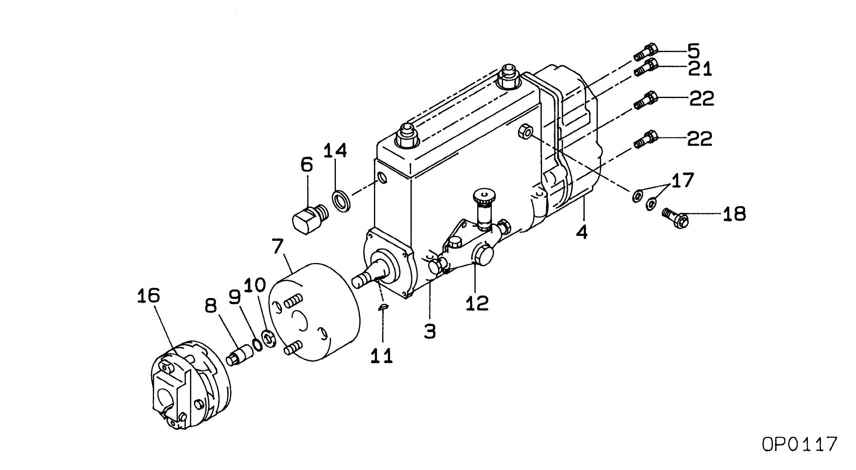
Components :
Scheme #.#:
№
Qty
Part num
Name
Remarks
Manufacture num
000
[01]
19100-01491
PUMP ASSY, INJECTI
NB6,RSV
22030-2021
HINO
000
[01]
19100-01491
PUMP ASSY, INJECTI
NB6,RSV
S2203-02021
HINO
Include in ##:
19100-01491
as PUMP ASSY, INJECTI
19100-01491 PUMP ASSY, INJECTI
Cross reference number
Part num
Firm num
Firm
Name
19100-01491
22030-2021
PUMP ASSY, INJECTI
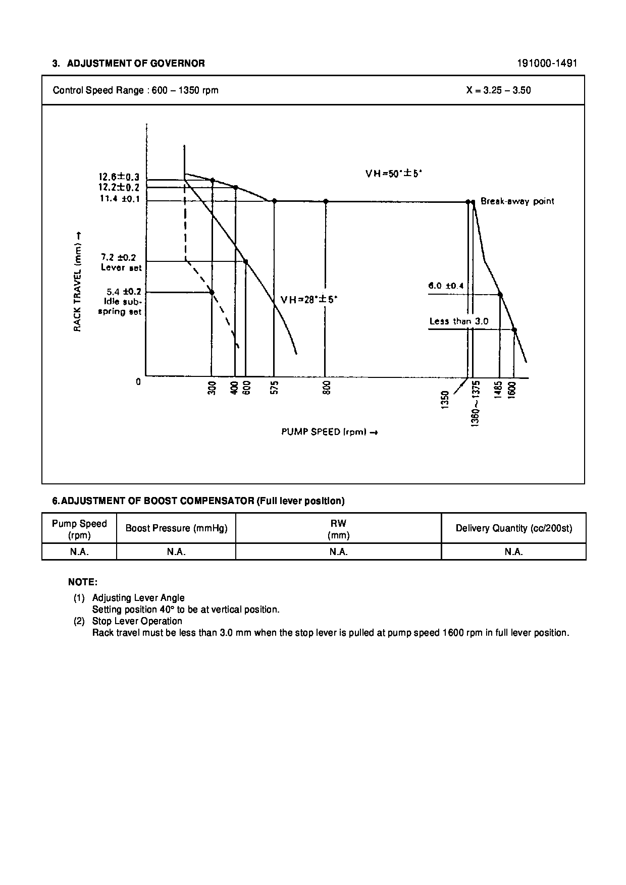
Test Calibration Data:
1910001490
22030-2021
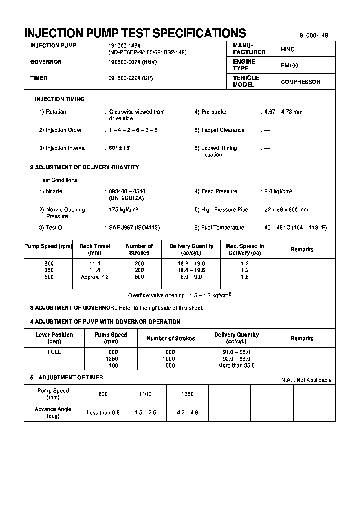
1910001491
22030-2021
Information:
Introduction
There have been some isolated instances of issues with fuel injection pumps on certain 3054C, C3.3, C4.4 (Mech), and C7.1 (Mech) engines. These issues with the fuel injection pump cause the engine to suffer from low power, issues with starting the engine, and excessive smoke.Solution
Ensure that the correct diagnosis procedures have been carried out. Ensure that the following tests have been carried out. Refer to Systems Operation Testing and Adjusting for further information.
Fuel System - Inspect
Air in Fuel - Test
Fuel Injection Nozzle - Test
Fuel Quality - Test
Fuel System - Prime
Fuel System Pressure - TestIf the diagnosis procedures determine that the fuel injection pump has an issue, remove the fuel injection pump from the engine. Refer to Disassembly and Assembly, "Fuel Injection Pump - Remove" for the correct procedure. Once the fuel injection pump is removed, follow step1 to step 9 to inspect the fuel injection pump.
Personal injury can result from being struck by parts propelled by a released spring force.Make sure to wear all necessary protective equipment.Follow the recommended procedure and use all recommended tooling to release the spring force.
Care must be taken to ensure that fluids are contained during performance of inspection, maintenance, testing, adjusting and repair of the product. Be prepared to collect the fluid with suitable containers before opening any compartment or disassembling any component containing fluids.Dispose of all fluids according to local regulations and mandates.
If possible, take the fuel injection pump to a clean work area.
Clean the outside surfaces of the fuel injection pump.
Illustration 1 g03117860
Typical example
Place a suitable container under the fuel injection pump to collect any fuel from the fuel injection pump. Use a suitable tool to loosen the drain plug (1). If necessary, retain the fuel collected for analysis if required.
Illustration 2 g03117878
Typical example
Use a suitable pair of pliers to remove the throttle return spring (2).Note: Care should be taken when the spring is removed.
Illustration 3 g03117896
Typical example
Loosen self-locking nut (3). Do not remove the nut.
Illustration 4 g03117916
Typical example
Use a suitable pair of pliers to lift and disconnect throttle spring (4). Remove self-locking nut (3), washer, upper retainer, spring, lower retainer, spacer, lever, and dust cap.Note: Care should be taken when the spring is removed.
Illustration 5 g03117938
Typical example
Remove four screws (6) in the governor cover (7). Gently push the throttle shaft (5) down into the cover (7).
Illustration 6 g03117956
Typical example
To inspect the internal components of the fuel injection pump, gently lift and rotate the cover (7).Note: The cover is still connected internally, if resistance is felt, lo