Rating:
Information pump assy, injecti Denso
Product
Fuel Injection Pump
Vehicle engine
INDUSTRIAL SA6D140
Engine
SA6D140
Serial start-end
8511--8712
Info
Injector Nozzle
093500-3080
Injector nozzle:
0935003080
KIT List:
Part name
Kit1
Kit2
Components :
Scheme #.#:
№
Qty
Part num
Name
Remarks
Manufacture num
000
[01]
19100-01360
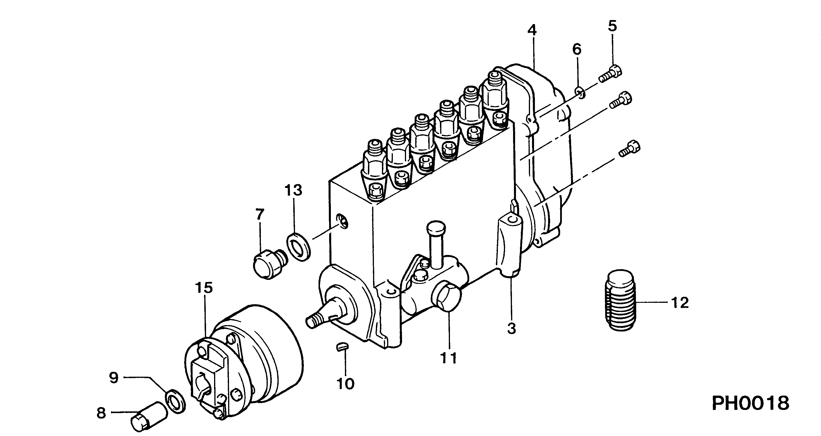
PUMP ASSY, INJECTI
NE6,RSUV
-8810
Include in ##:
19100-01360
as PUMP ASSY, INJECTI
Cross reference number
Part num
Firm num
Firm
Name
19100-01360
PUMP ASSY, INJECTI
Information:
Table 1
Part Number Changes for 226-7579 Fuel Lines Gp
QTY New Part Number Description Former Part Number
1 488-9360 Hose As 236-5242
1 488-9361 Hose As 136-3310
1 488-9362 Hose As 240-8598
1 148-8354 Elbow As 148-8364
9 6D-4244 Clip 1S-0994
1 329-1681 Clip 1S-1015
2 383-6118 Clip 5K-5338
1 5P-4295 Clip 9M-8406 Use the following procedure to update the fuel lines group with the new hose assemblies.Note: Follow all the safety precautions before carrying out any work on the machine.Installation of 488-9360 Hose As between Fuel Tank and Primary filter group
Illustration 1 g06107286
View of inner side of left-hand frame
(A) Fuel tank
(1) 488-9360 Hose As
(2) 383-6118 Clip
Remove former 236-5242 Hose As from fuel tank (A) along the left-hand inner frame and replace with 488-9360 Hose As (1). Use two 383-6118 Clips (2) to mount 488-9360 Hose As (1) to the inner frame.
Illustration 2 g06107793
View of hose routing above the steering box assembly
(1) 488-9360 Hose As
(3) 6D-4244 Clip
Continue routing 488-9360 Hose As (1) above the steering box assembly from left to right using two 6D-4244 Clips (3) in place of the former 1S-0994 Clips.
Illustration 3 g06107808
View of hose routing to the primary filter group
(1) 488-9360 Hose As
(3) 6D-4244 Clips
Route 488-9360 Hose As (1) along the frame and up toward the primary filter group using 6D-4244 Clips (3) to secure to the frame.
Illustration 4 g06108256
View of primary filter group location inner side of right-hand frame
(B) Former fitting
(C) Primary filter group
(1) 488-9360 Hose As
(4) 148-8354 Elbow As
If not previously completed, remove former hose (B) along with the related fitting from the connection on primary filter group (C).
Connect 148-8354 Elbow As (4) onto primary filter group (C) where fitting (B) was removed.
Attach 488-9360 Hose As (1) to 148-8354 Elbow As (4).Installation of 488-9362 Hose As Between Fuel Tank and Fuel Return Manifold
Illustration 5 g06108268
View of left inner frame
(D) Former hose 240-8598 Hose As
Remove former return hose assembly (D) from between the fuel tank and the fuel manifold in the engine.Note: Unless specified otherwise, retain all mounting hardware for reuse.
Illustration 6 g06108327
View of new hose route.
(A) Fuel tank
(2) 383-6118 Clip
(5) 488-9362 Hose As
Connect 488-9362 Hose As (5) to fuel tank where the old hose was removed.
Route 488-9362 Hose As (5) back along the left-hand inner frame towards the engine and use two 383-6118 Clips (2) installed previously to secure hose assembly (5) in place.
Illustration 7 g06112935
View of the rear of the engine
(5) 488-9362 Hose As
(6) 9M-8406 Clip
(7) 329-1681 Clip
Finish installing 488-9362 Hose As (5) by routing hose (5) up the rear side of the engine and connecting the hose where former hose (D) was removed.
Secure 488-9362 Hose As (5) using one 9M-8406 Clip (6) and one