Rating:
Information pump assy, injecti Denso
Product
Fuel Injection Pump
Vehicle engine
INDUSTRIAL 6D125
Engine
6D125
Serial start-end
8506--8512
Info
Injector Nozzle
093500-2710
Injector nozzle:
0935002710
KIT List:
Part name
Kit1
Kit2
Components :
Scheme #.#:
№
Qty
Part num
Name
Remarks
Manufacture num
Cross reference number
Part num
Firm num
Firm
Name
19100-00870
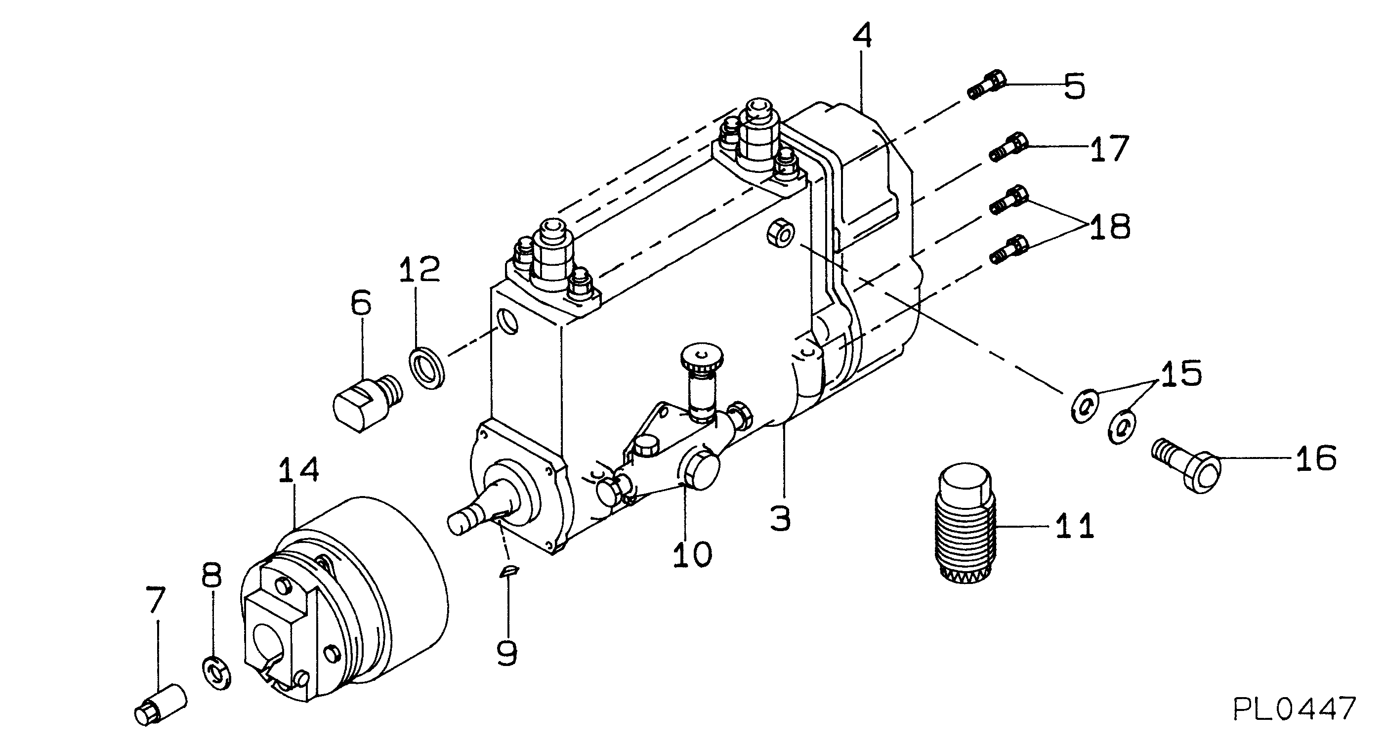
PUMP ASSY, INJECTI
Information:
Turn the engine to (TDC) top center compression stroke for the No. 1 piston and install crankshaft flywheel timing pin. This will help when timing the camshaft when installing.
Wire used to hold cam roller followers up off camshaft. It is not necessary to remove the cylinder head. With the cylinder head in place, just wire the cam roller followers up off the camshaft and then remove the camshaft. 1. Remove camshaft retainer bolt (1) and remove camshaft assembly (2). The following steps are for the installation of the camshaft assembly. When installing the camshaft, rotating it both clockwise and counter clockwise directions will help prevent it from binding in the bearing bores.2. Put engine oil on the lobes and journals of the camshaft. Carefully install the camshaft. When installing the camshaft, be sure the number one cylinder is at (TDC) top dead center of the compression stroke with the timing pin installed in the flywheel. Camshaft timing is very important. Cam gear timing marks must line up with idler gear timing marks as illustrated. For more information about timing of engine, refer to SPECIFICATIONS module, FORM No. SENR3908.
Camshaft Timing3. With the camshaft properly timed and positioned, install retaining bolt (1). Tighten bolt (1) to a torque of 48 7 N m (35 5 lb.ft.). Remove the wire that was used to hold the cam roller followers up off the camshaftEnd By:a. install fuel transfer pumpb. install front coverc. install front pulley and damperd. install fuel injectorse. install rocker arm assemblies and push rodsDisassembly And Assembly of Camshaft And Gear/Weight Assembly
If the disassembly is being done, just to replace any or all of the twelve retainers, then it may not be necessary to remove the weight assembly from the camshaft. Depending on the press set-up, the retainers may be removed and installed with the camshaft and weight assembly still assembled.Start By:a. remove camshaft assembly 1. Wrap camshaft portion of camshaft and gear/weight assembly (1) with paper towels (2) to protect the camshaft from being damaged. Remove bolts (3) and remove cover plate (4) from assembly (1). Care must be taken not to damage the timing/speed sensor ring gear when removing. Using the prybar, work around the ring gear and pry the ring gear off a little at a time. 2. Using a prybar, carefully pry timing/speed sensor ring gear (5) off the gear/weight assembly. 3. Reposition the camshaft and gear/weight assembly. Remove bolts (6) and remove retainer ring (7), then remove cam gear (8).
Care must be taken not to allow the camshaft to fall to the floor when pressing it from the weight. Also be sure that a camshaft lobe does not catch on the press plates.
4. Place the camshaft and weight assembly through spacer pipe (10) and place it in the press as illustrated. Press the camshaft from weight assembly (9). 5. Position weight assembly (9) in press as illustrated. Use a small spacer pipe (11) to support weight (9) and with a block on