Rating:
Information pump assy, injecti Denso
Product
Fuel Injection Pump
Vehicle engine
INDUSTRIAL EM100
Engine
EM100
Serial start-end
8501--8512
Info
Injector Nozzle
093500-2180
Injector nozzle:
0935002180
KIT List:
Part name
Kit1
Kit2
Components :
Scheme #.#:
№
Qty
Part num
Name
Remarks
Manufacture num
Cross reference number
Part num
Firm num
Firm
Name
19100-00600
PUMP ASSY, INJECTI
1910000600
22030-1690
HINO
PUMP ASSY, INJECTI

Information:
1. Disconnect water supply hose from water pump inlet.2. Remove connector pipe (1), remove two bolts (2) and remove oil fill pipe (3). 3. Remove bolts (4) and (5) then remove the water pump. The following steps are for the installation of the water pump.4. Position the water pump and install two bolts (4) and (5). Tighten the two bolts evenly.5. Position connector pipe (1) and gaskets then install the bolts.6. Install oil fill pipe (3). Be sure the gasket is in position between the regulator and pipe and install bolts (2).End By:a. Install alternatorb. Fill the cooling system to the specified level. See the Maintenance ManualDisassemble & Assemble Water Pump
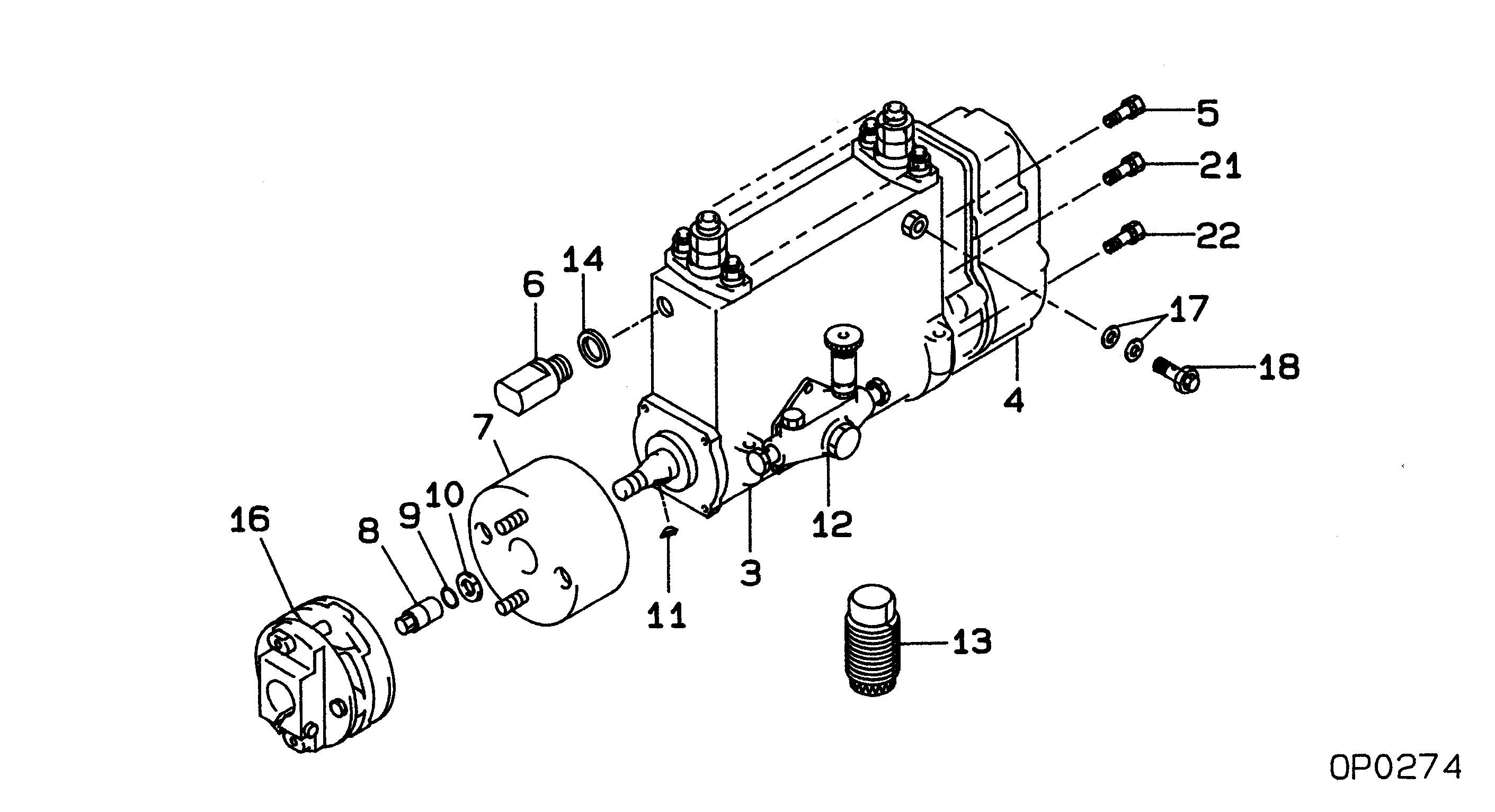
Start By:a. remove water pump 1. Remove three bolts (1) and remove cover (2). 2. Use an M12 X 1.75 bolt to force impeller (3) from shaft (4). Install forcing bolt in impeller as indicated by arrow. Hold impeller and screw bolt in until impeller comes off shaft. 3. Remove bolt (5), washer (6), bearing (7) and gear (8). 4. Remove three bolts (9) and remove cover (10) with bearing (11). 5. Press shaft (4) out of seal (12).
Do not allow shaft (4) to fall to the floor, damage may occur to the shaft.
6. Remove seal (12) and seal (13) from water pump housing. The following steps are for the assembly of the water pump. 7. Using driver group, install seal (13). Refer to illustration to see direction of seal lip. Lubricate shaft seal area with engine oil.8. Assemble shaft (4), bearing (11) and cover (10). Position assembly into seal and housing then install bolts (9). 9. Position the housing and shaft assembly in a press. Position seal (12) on shaft (4). 10. Position tool (A) and press seal into place. 11. Position the water pump in a press, position impeller (3) and press it into place. Dimension X is 1.5 0.5 mm (.059 .020 in).12. Position seal and cover (2), then install bolts (1).End By:a. install water pump