Rating:
Information pump assy, injecti Denso
Product
Fuel Injection Pump
Vehicle engine
INDUSTRIAL EM100
Engine
EM100
Serial start-end
8401--9501
Info
Injector Nozzle
093500-2180
Injector nozzle:
0935002180
KIT List:
Part name
Kit1
Kit2
Components :
Scheme #.#:
№
Qty
Part num
Name
Remarks
Manufacture num
000
[01]
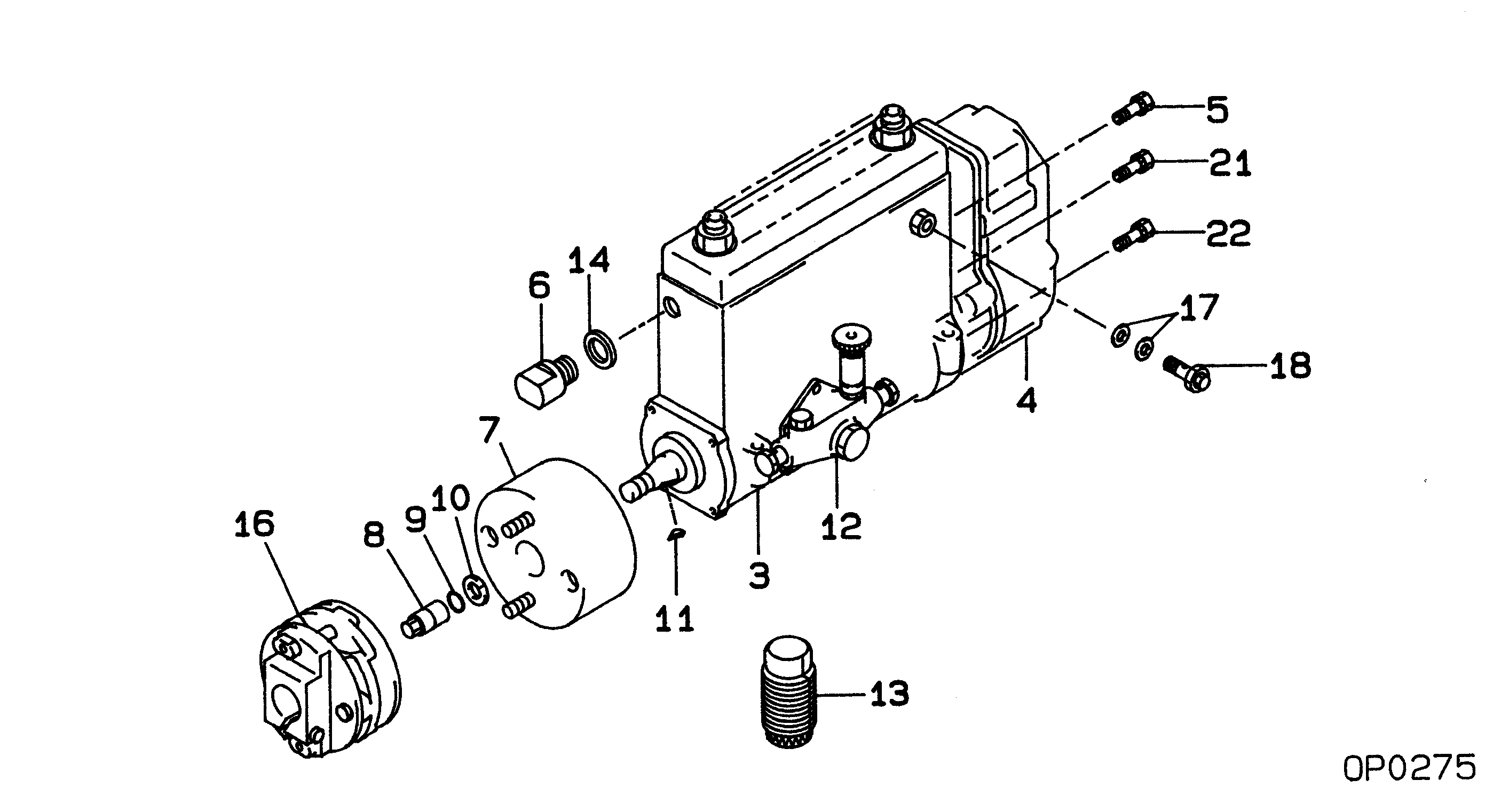
19000-08050
PUMP ASSY, INJECTI
NB6,RSV
22030-1541
HINO
Include in ##:
19000-08050
as PUMP ASSY, INJECTI
Cross reference number
Part num
Firm num
Firm
Name
19000-08050
22030-1541
PUMP ASSY, INJECTI
1900008050
22030-1541
HINO
PUMP ASSY, INJECTI
Information:
The red lamp should stay ON to indicate that the engine is not protected if the switch is left in the OFF position after the repairs have been made.
Alarm Testing
During testing, abnormal operating conditions must be simulated. Perform the tests correctly to prevent possible damage to the engine.
All alarms on the engine should be tested twice a year for proper operation by referring to the Service Manual and/or contacting your authorized Caterpillar dealer.The controls should be tested every 1000 hours by authorized Caterpillar dealer personnel. Every 500 hours, the Hydramechanical Shutoff (HMSO, early engines) can be tested remotely by engine personnel.Determining Cause of Shutdown or Alarm
There are different conditions that may cause the alarm systems, usually found on an engine, to be activated. Causes for the alarm to function should be followed by performing corrective measures. Additional measures may be required by the operator, depending upon circumstances and conditions present. An authorized Caterpillar dealer should analyze major engine problems. On multi-engine powered vessels, one engine may be shut down for repairs while proceeding at reduced power on the remaining engine(s).Alarm Contactors
The engine is equipped with standard electrical overspeed switch which uses a flywheel housing mounted magnetic pickup. The magnetic pickup will close the circuit and the alarm will be activated when the engine exceeds the setpoint rpm. This engine may be equipped with a Coolant Level Alarm contactor. An Oil Pressure and Coolant Temperature Alarm contactors are optional.Alarm switches are electrically connected to an indicator light, bell or horn. When an alarm is activated, it is an indication of a potential problem and corrective measures must be taken before the situation becomes an emergency. While these alarm switches do not stop the engine, the problem should be investigated and corrective action taken to prevent engine damage.The alarm will continue until the condition is corrected. Then the light will turn off and the bell or horn will be silenced.To silence the bell or horn while repairs are being made, a two-way switch and a red indicator light may be installed. The red indicator light will come on when the alarm is turned off. The red light will stay on, to indicate that the engine is NOT protected, if the switch is left in the OFF position after the repairs have been made.Low Oil Pressure Switch (Early Engines)
The switch will not protect the system from rapid oil loss, caused by failures such as line breakage.
Low oil pressure switchThis device is usually mounted on the side of the engine. The oil lines are connected to the switch. Low oil pressure closes the switch. To reset the switch, push the RESET button in the junction box until it latches. After the engine starts and develops oil pressure, the button will move to the extended (running) position.
The button must be in the RUN position to protect the engine. If the button remains in the OFF position, the engine oil pump may not be developing normal oil pressure and proper checks should be made.
Manually