Rating:
Information pump assy, injecti Denso
Product
Fuel Injection Pump
Vehicle engine
TRUCK EH700
Engine
EH700
Serial start-end
8403--8608
Info
Injector Nozzle
093500-2080
Injector nozzle:
0935002080
KIT List:
Part name
Kit1
Kit2
Components :
Scheme #.#:
№
Qty
Part num
Name
Remarks
Manufacture num
000
[01]
19000-06460
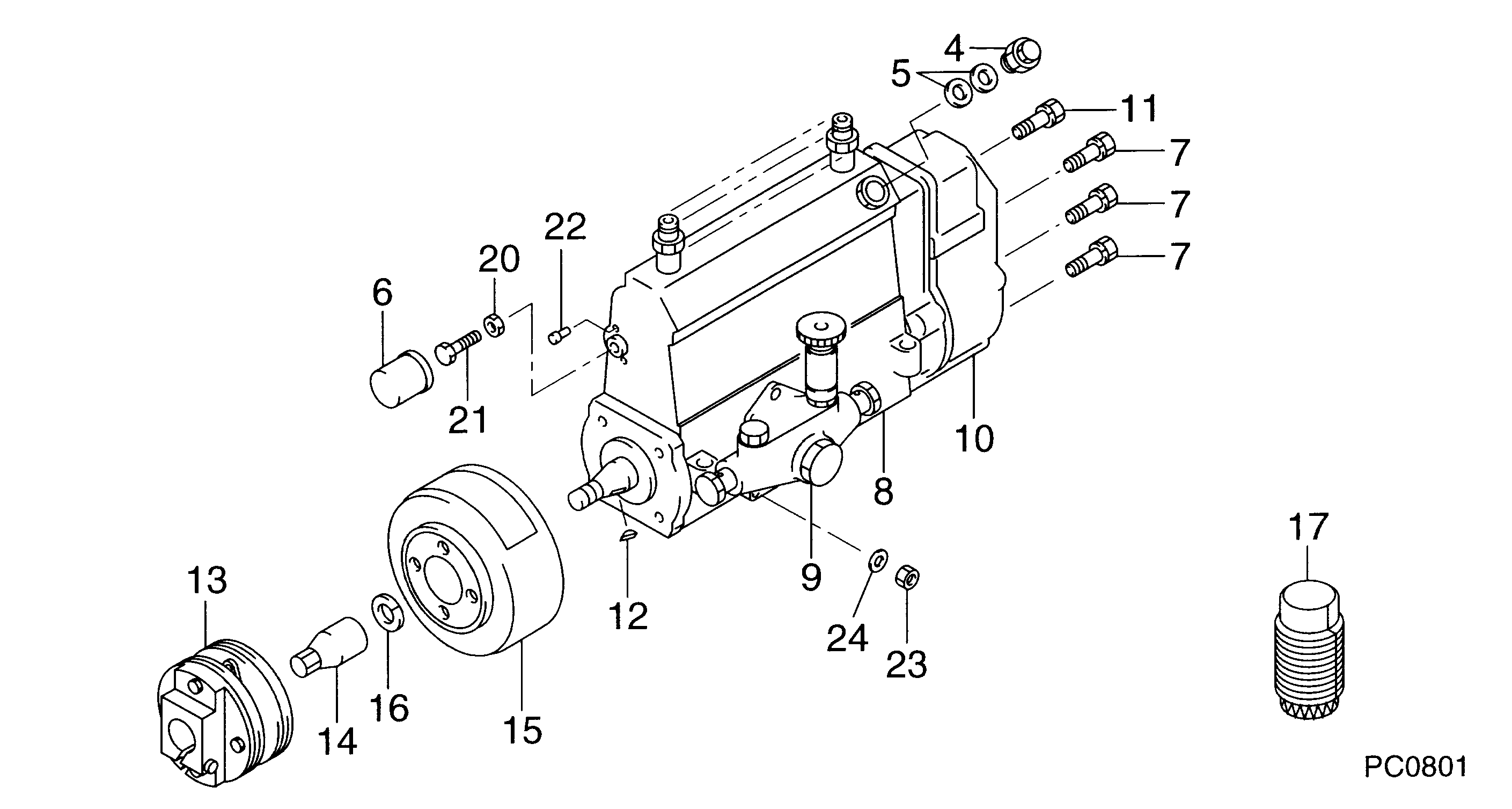
PUMP ASSY, INJECTI
A6,R722
22010-3050
HINO
Include in ##:
19000-06460
as PUMP ASSY, INJECTI
Cross reference number
Part num
Firm num
Firm
Name
19000-06460
22010-3050
PUMP ASSY, INJECTI
1900006460
22010-3050
HINO
PUMP ASSY, INJECTI
Information:
Keep all parts clean from contaminants. Contaminants put into the system may cause rapid wear and shortened component life.
1. Remove the coolant from the cylinder block.2. Put covers on journals of crankshaft to protect from dirt or water. 3. Remove cylinder liners (1) with tooling (A).Install Cylinder Liners
1. Clean the cylinder liners (1) and the liner bores in the cylinder block.2. Install the cylinder liners in the block without the O-ring seals or filler bands.3. Check the cylinder liner projection as follows:a. Install the S1589 Bolts (2) and 1S379 Washers of tooling (B) on the cylinder block next to each liner. Tighten the bolts evenly, in four steps: 14 N m (10 lb ft), 35 N m (25 lb ft), 70 N m (50 lb ft) and 95 N m (70 lb ft).b. Put adapter plate on top of the liner and install the remainder of tooling (B). Tighten the 1D4595 Bolts (3) evenly in four steps: 7 N m (5 lb ft), 20 N m (15 lb ft), 35 N m (25 lb ft) and 70 N m (50 lb).c. Check to be sure the distance from the bottom edge of the crossbar to the top of the cylinder block is the same on both sides of the liner.d. Check the cylinder liner projection with tool group (C) at four locations around the liner.e. Liner projection must be 0.033 to 0.175 mm (.0013 to .0069 in). Measurements on the same liner must not be different by more than 0.05 mm (.002 in). Average measurements between liners next to each other must not be different by more than 0.05 mm (.002 in). If the liner is turned in the bore, it can make a difference in the liner projection.4. If the liner projection is not 0.033 to 0.175 mm (.0013 to .0069 in), check the thickness of the following parts: spacer plate, spacer plate gasket and cylinder liner flange. The thickness of the spacer plate must be 9.970 0.025 mm (.3925 .0020 in). The thickness of the spacer plate gasket must be 0.208 0.025 mm (.0082 .0010 in). The thickness of the cylinder liner flange must be 10.282 0.020 mm (.4048 .0008 in). Cylinder liner projection can be adjusted by the removal of material from (machining) the contact face of the cylinder block with the use of the 8S3140 Cylinder Block Counterboring Tool Arrangement. Machine to a minimum depth of 0.76 mm (.030 in) and to a maximum depth of 1.14 mm (.045 in). The instructions for the use of the tool group are in Special Instruction, Form No. FM055228. Shims are available for the adjustment of the liner projection. See the topic, Cylinder Liner Projection in Testing And Adjusting, for the shim thickness and part number.5. Remove tooling (B) and (C). Remove the liner. 6. Put liquid soap on bottom liner bore in block, on grooves in lower liner and on O-ring seals on the liner.7. Put filler band (5) in