Rating:
Information pump assy, injecti Denso
Product
Fuel Injection Pump
Vehicle engine
TRUCK EH700
Engine
EH700
Serial start-end
8110--8201
Info
Injector Nozzle
093500-2110
Injector nozzle:
0935002110
KIT List:
Part name
Kit1
Kit2
Components :
Scheme #.#:
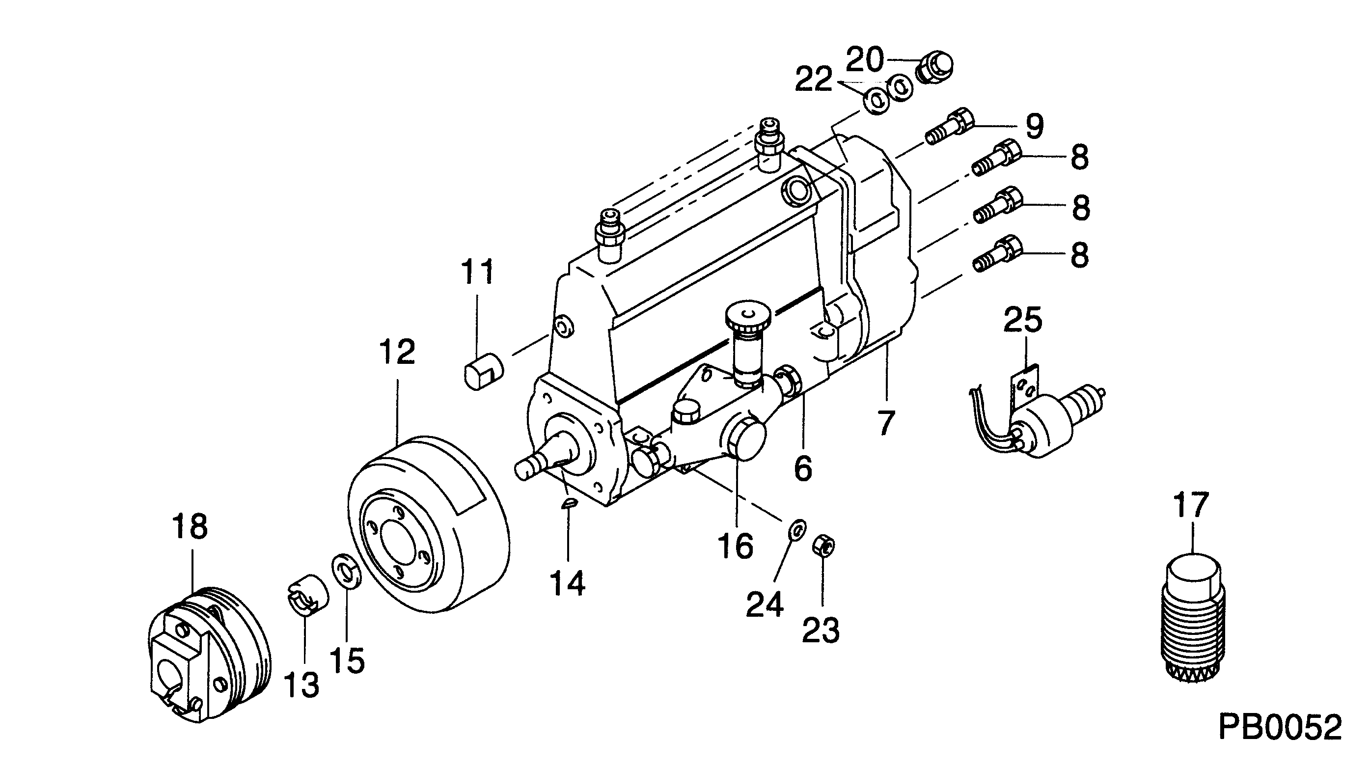
№
Qty
Part num
Name
Remarks
Manufacture num
000
[01]
19000-06340
PUMP ASSY, INJECTI
A6,R721
22010-2930
HINO
Include in ##:
19000-06340
as PUMP ASSY, INJECTI
Cross reference number
Part num
Firm num
Firm
Name
19000-06340
22010-2930
PUMP ASSY, INJECTI
1900006340
22010-2930
HINO
PUMP ASSY, INJECTI
Information:
Keep all parts clean from contaminants. Contaminants put into the system may cause rapid wear and shortened component life.
1. Put compression on valve spring (2) with tool (A), and remove locks (1).2. Remove tool (A), rotocoil, spring, valve stem oil shield and valve. Put identification marks on valves with respect to their location in the cylinder head. 3. Check the spring force with tool (B). The spring force is 257 25 N (57.8 5.6 lb.). The length of spring under test force is 44.86 mm (1.766 in). The free length after test is 52.07 mm (2.050 in).4. Perform Steps 1 through 3 again for the remainder of the valves. The following steps are for the installation of the valves.5. Put clean engine oil on the valve stems. Install the valve, oil shield, spring (2) and rotocoil in the cylinder head. 6. Put tool (A) in position on the valve spring, and install the locks with tool (C).
Locks can be thrown from valve when the compressor is released if they are not in their correct position on valve stem. Personal injury can be the result if not carefully removed.
7. Remove tool (A), and hit the top of valve with a plastic hammer be sure the locks are in their correct position on valve.8. Do Steps 5 through 7 again for the remainder of the valves.End By:a. install spacer plate