Rating:
Information pump assy, injecti Denso
Product
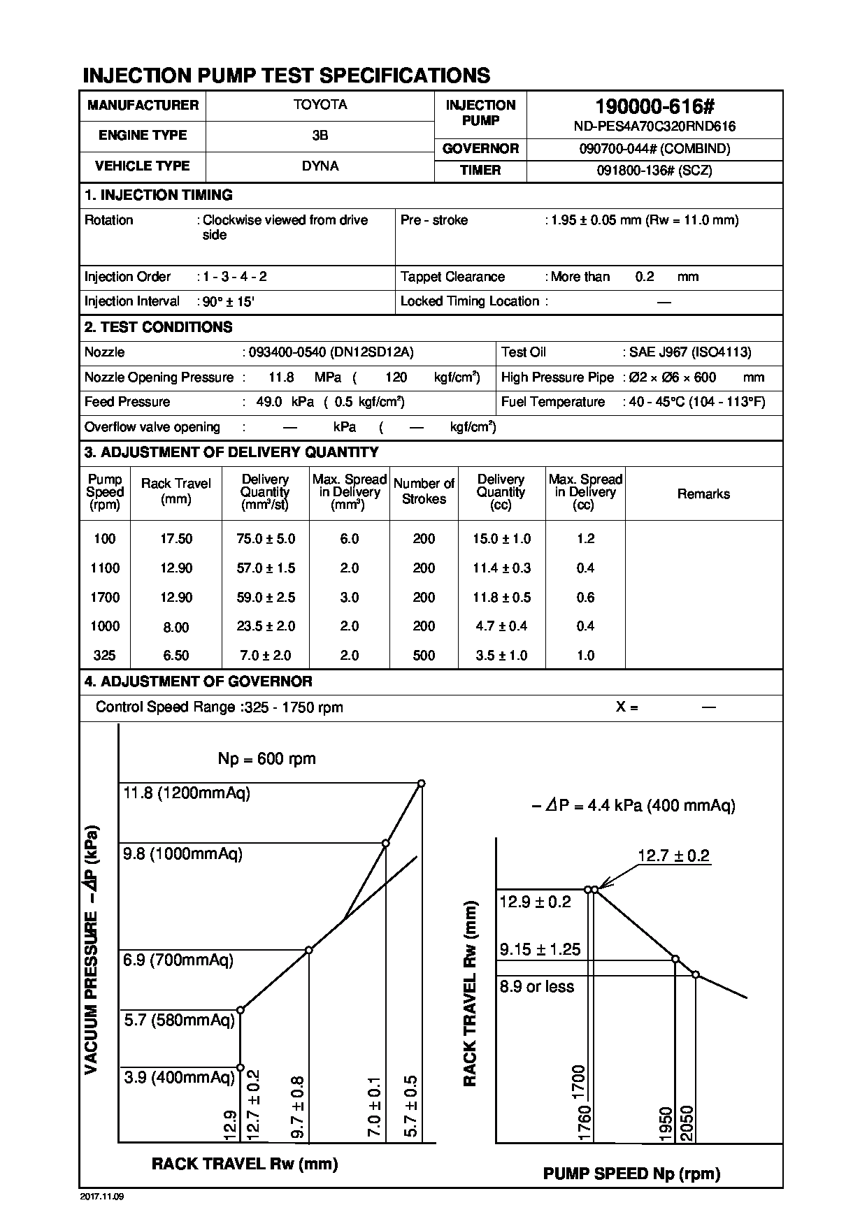
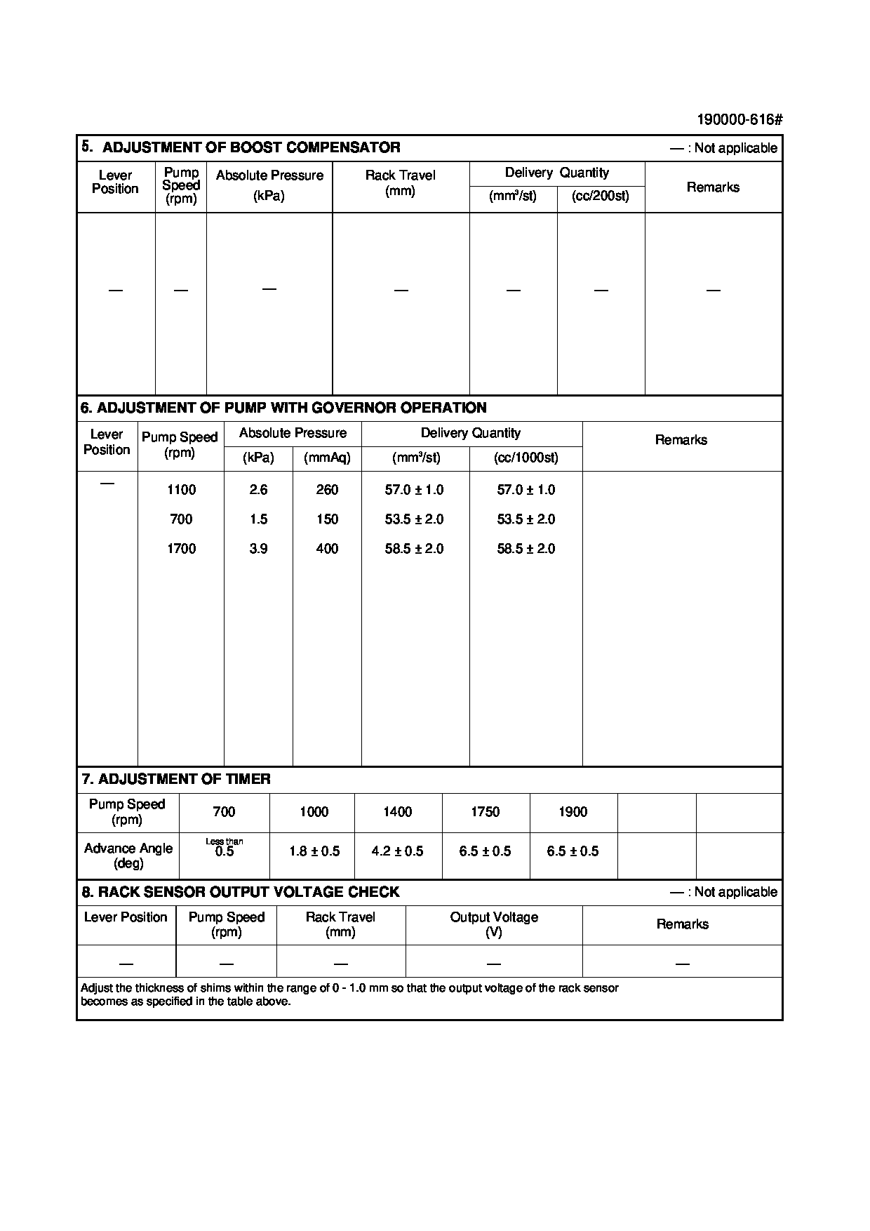
Fuel Injection Pump
Vehicle engine
DYNA 3B
Engine
3B
Serial start-end
8111--8410
Info
Injector Nozzle
093500-2370
Injector nozzle:
0935002370
KIT List:
Part name
Kit1
Kit2
Components :
Scheme #.#:
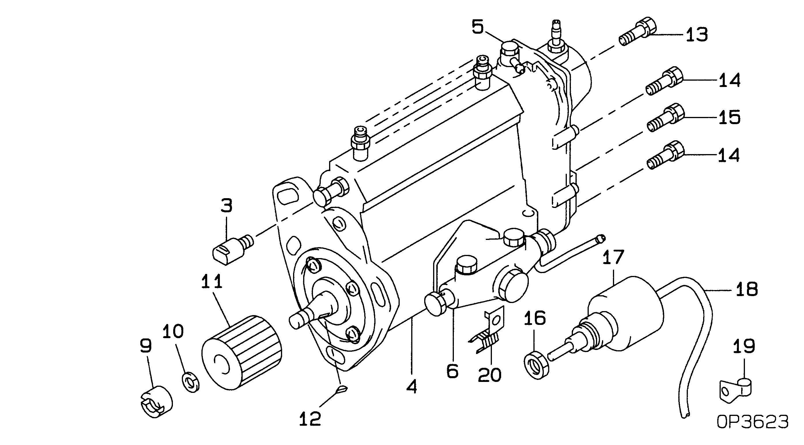
№
Qty
Part num
Name
Remarks
Manufacture num
000
[01]
19000-06160
PUMP ASSY, INJECTI
A4 COMBINED
22100-58071
TOYOTA
Include in ##:
19000-06160
as PUMP ASSY, INJECTI
Cross reference number
Part num
Firm num
Firm
Name
19000-06160
22100-5807
PUMP ASSY, INJECTI
1900006160
22100-58071
TOYOTA
PUMP ASSY, INJECTI
Information:
1. Disconnect pressure line (3). Remove two bolts (2).2. Move fuel ratio control (1) up to disengage the fuel ratio control from the lever assembly in the governor. 3. Remove four O-ring seals (4) and screen assembly (5). The following steps are to install the fuel ratio control.4. Inspect, replace and install the four O-ring seals (4) and the screen assembly (5).5. Put the fuel ratio control (1) in position and engage the fuel ratio control with the lever assembly in the governor.6. Install the bolts that hold the fuel ratio control and connect pressure line (3) to the fuel ratio control (1). See Testing And Adjusting for Fuel Ratio Control Adjustment procedure.Disassemble And Assemble Fuel Ratio Control
Start By:a. remove fuel ratio control
Keep all parts clean from contaminants. Contaminants put into the system may cause rapid wear and shortened component life.
1. Remove the two bolts, and the fuel ratio control. Remove O-ring seal (1). 2. Put tooling (A) in a vise as shown so that the station being used is not over the vise jaw. Place the fuel ratio control over the pins in tooling (A). Remove cover (2) and the gasket.
There is spring force behind cover (3). Hold cover (3) in position, and slowly remove the bolts that hold it to release the spring force.
3. Remove cover (3). 4. Remove nut (5) and stop (6). 5. Remove spring (9), washer (7), and diaphragm (10) from retainer (8). Remove retainer (8) from housing (11). 6. Remove nut (16) from extension (15), and remove the extension from retainer (8). Remove valve (12), spring (13) and O-ring seal (14). 7. Remove spring (18), retainer (17) and spring (19). 8. Remove piston assembly (20). 9. Use tooling (B), and remove snap ring (21) and the wave washers from valve assembly (22). Remove piston assembly (23). Remove seal (24). 10. If necessary, remove stem (26) from valve (25).11. Clean and inspect all parts. Make a replacement of all parts that are worn or damaged. The following steps are to assemble the fuel ratio control.12. Assemble stem (26) to valve (25) using 9S3265 Retaining Compound.13. Put seal (24) on piston (23). Install piston (23) on valve assembly (22).14. Put two wave washers in position on valve (22). Use tooling (B) to install the snap ring on the valve assembly.15. Place housing (4) on tooling (A), and put tooling (C) into the bore of the housing. Lubricate tooling (C) with clean engine oil.16. Put a small amount of clean oil on the seal of the piston assembly, and push piston assembly (23) into position with a smooth swift motion.17. Place spring (9), retainer (17) and spring (19) in position in housing (4).18. Put O-ring seal (14) on extension (15). Put spring (13) and valve (12) in position on the extension.19. Lubricate O-ring seal (14) with clean engine oil. Install extension (15) in retainer (8). Install nut (16).20. Put diaphragm (10), washer (7) and spring (9) in position on retainer (8). Install retainer (8).21.