Rating:
Information pump assy, injecti Denso
Product
Fuel Injection Pump
Vehicle engine
FORKLIFT 2D
Engine
2D
Serial start-end
8007-
Info
Injector Nozzle
093500-1820
Injector nozzle:
0935001820
KIT List:
Part name
Kit1
Kit2
Components :
Scheme #.#:
№
Qty
Part num
Name
Remarks
Manufacture num
000
[01]
19000-04800
PUMP ASSY, INJECTI
A6,R721
22100-31633-71
TOYOTA
Include in ##:
19000-04800
as PUMP ASSY, INJECTI
Cross reference number
Part num
Firm num
Firm
Name
19000-04800
22100-3163
PUMP ASSY, INJECTI
1900004800
22100-31633-71
TOYOTA
PUMP ASSY, INJECTI
Information:
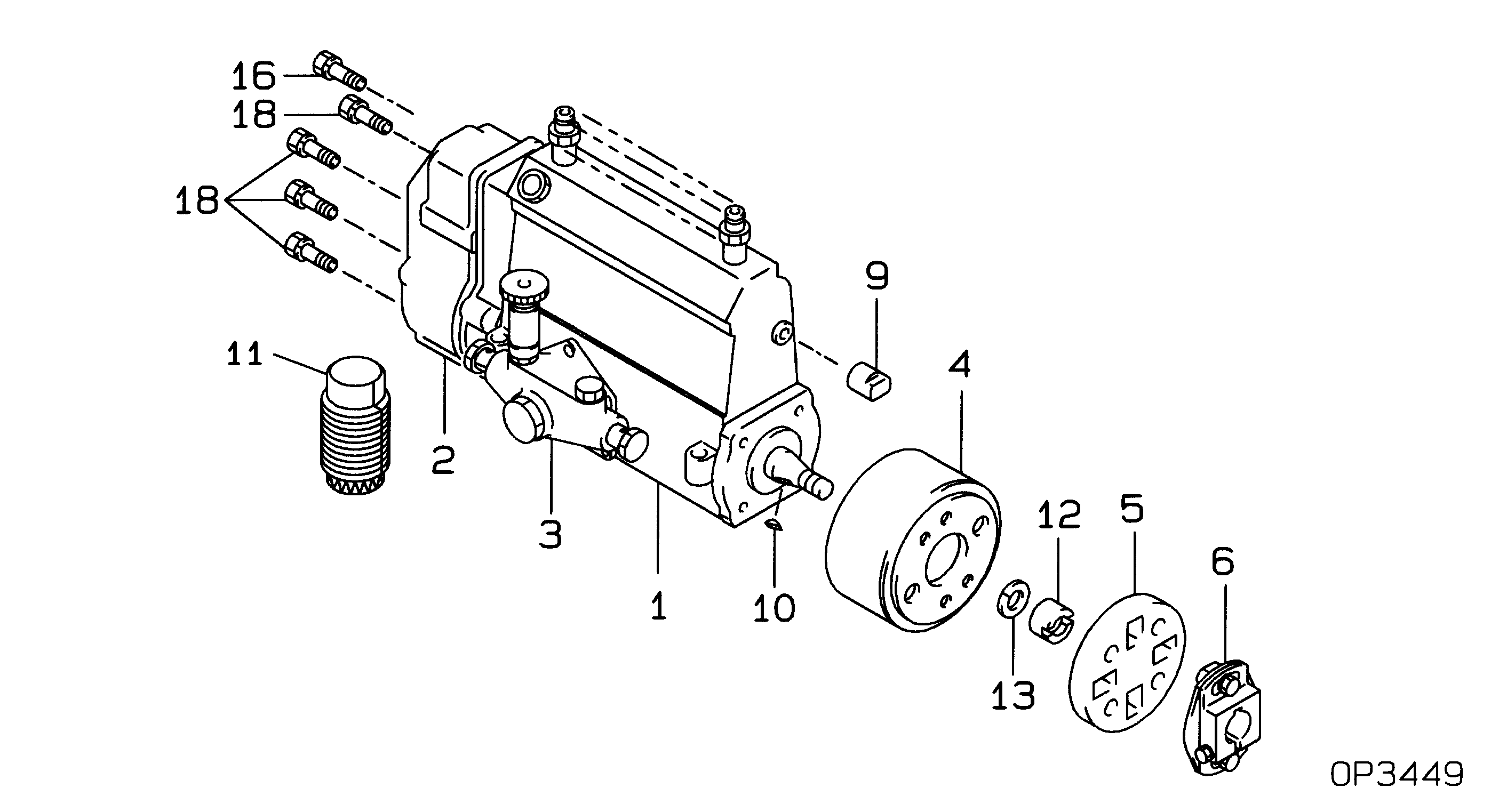
1. Remove coolant from the engine.2. Loosen two hose clamps (3) and slide hose from tube assembly (2).3. Disconnect tube assembly (1) at the aftercooler cover.4. Remove four bolts holding the tube assembly to the aftercooler housing. Remove tube assembly (2). 5. Remove O-ring seal (4). 6. Remove adapter (5) and the gasket. An O-ring seal on each end of the aftercooler core holds the adapters (5) and (13) in position. 7. Loosen hose clamps (6) and slide hose on the breather tubes. Remove bolt (8) and breather tube (7). 8. Disconnect hose assembly (9).9. Loosen hose clamps (11) and slide the hose from tube assembly (10).10. Remove four bolts fastening the tube assembly to the aftercooler cover. Remove tube assembly (10). 11. Remove O-ring seal (12). 12. Remove adapter (13) and the gasket. 13. Remove the four bolts (14). 14. Remove bolts (17), cover (18) and the gasket. Remove pipe (16). 15. Remove aftercooler core assembly (20) and the gasket. Remove "O'-ring seals (19) from each end of the core. 16. Remove two bolts (21) on the inside of the aftercooler housing. Make a note of the location of bolt spacers before removal. 17. Remove bolts and spacers (23), housing (22) and the gasket. The following steps are to install the jacketwater aftercooler. Inspect all O-ring seals and gaskets and make replacements if necessary. Put a thin layer of clean engine oil on all O-ring seals and in the bores of each adapter.18. Put aftercooler housing gaskets in position on the cylinder head and install aftercooler housing (22). Make a note of the location of two bolts and spacers (23) from the remove story Step 17.19. Install aftercooler core gasket (20).20. Install the O-ring seals (19) on each end of the aftercooler core (20).21. Put the aftercooler core (20) in position in the housing. Put the gasket in place on the core assembly.22. Install turbocharger pipe and the aftercooler cover (18).23. Install four bolts to fasten flange (15) to cover.24. Install gasket and adapter (13). Install breather tube on breather assembly and install the bolt to fasten the breather tube clip to the engine oil cooler.25. Install O-ring seal (12).26. Install tube assembly (10). Slide hose in position and tighten hose clamps.27. Connect hose assembly (9) to tube assembly (10).28. Install gasket and adapter (5).29. Install O-ring seal (4) on tube assembly (2).30. Put tube assembly (2) in position on housing. Make sure tube assembly clip is in place and install the bolts.31. Slide hose in position and tighten two clamps (3).32. Connect tube assembly (1).33. Fill the radiator to the correct level with coolant.
Perform Scheduled Oil Sampling after performing service work to check for coolant leakage and contaminants left in the system following repair. Contaminants put into the system may cause rapid wear and shortened component life.
Perform Scheduled Oil Sampling after performing service work to check for coolant leakage and contaminants left in the system following repair. Contaminants put into the system may cause rapid wear and shortened component life.