Rating:
Information pump assy, injecti Denso
Product
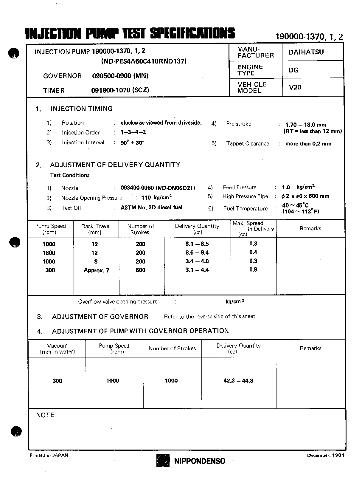
Fuel Injection Pump
Vehicle engine
DELTA DG
Engine
DG
Serial start-end
7708--7908
Info
Injector Nozzle
093500-1760
Injector nozzle:
0935001760
KIT List:
Part name
Kit1
Kit2
Components :
Scheme #.#:
№
Qty
Part num
Name
Remarks
Manufacture num
Cross reference number
Part num
Firm num
Firm
Name
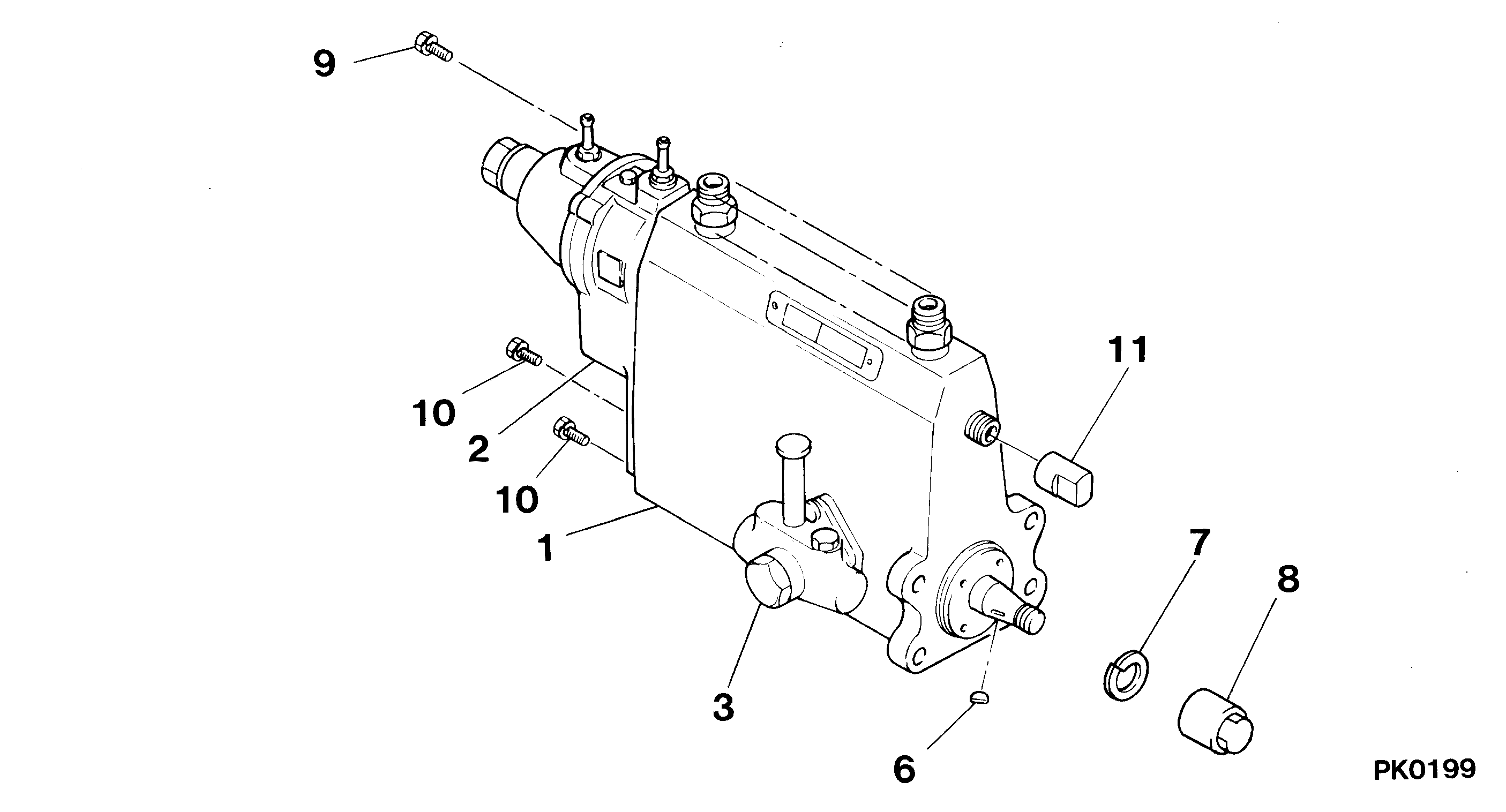
19000-01370
PUMP ASSY, INJECTI
Information:
Start By:a. remove cylinder headb. remove oil panc. remove cooling jets 1. Remove two rod cap bolts (1) from each rod. Remove rod caps (2).2. Using a soft hammer tape rod (3) away from crankshaft and remove bearing half (4). When removing cylinder pack, watch the rod and prevent it from catching on the block bore as it comes out.3. Install tooling (A) and remove cylinder pack (5). 4. Remove cylinder liner seal (6) at the base of the spacer block. 5. Remove the remainder of tooling (A) from cylinder pack (5) and then remove the rod and piston from the cylinder liner. The following steps are for the installation of the cylinder pack.6. Install a new cylinder liner seal, lubricate the seal with engine oil. Some engines use pistons which have the word "FRONT" stamped on the crown of the piston. Make sure the word "FRONT" is toward the front of the engine when the piston is installed. The etched number on the connecting rod must be on the right side and must be installed in the corresponding cylinder. Paint a thin coat of 9U-5839 Liquid Gasket at the very bottom of the seal flange on the cylinder liner. Allow the Liquid Gasket to dry to touch. Do not apply Liquid Gasket between the engine spacer block and cylinder block surfaces. Using excessive amounts of liquid gasket material on the liner flange seat can cause oil leaks due to distortion of the o-ring seals between the spacer block and cylinder block.7. Lubricate the lower portion of the cylinder liner with engine oil. Be sure the corresponding crankshaft throw is at bottom center. Position cylinder pack (5) and guide rod (3) into place. Use Tooling (B) and press cylinder (5) into place.8. With rod (3) in this position, install the upper half of rod bearing (4). Be sure the bearing tab properly engages the slot in the connecting rod. Lubricate the bearing surface with engine oil and tap the piston down with a rubber mallet until the rod and bearing contacts the crankshaft.9. With rod cap bearing in place and oiled, install rod cap (2). Lubricate rod bolts (1) with 2P-256 Thread Lubricant. Install rod bolts (1) and torque to 130 7 N m (95 5 lb ft). Mark each bolt head and then tighten each bolt by an additional 60 5° (1/6 turn).End By:a. Install cooling jets.b. Install oil pan.c. Install cylinder head.