Rating:
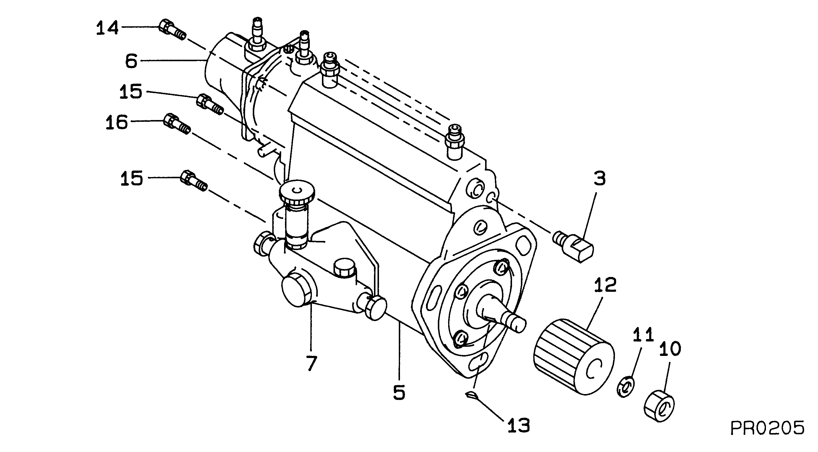
Information pump assy, injecti Denso
Components :
Scheme #.#:
№
Qty
Part num
Name
Remarks
Manufacture num
000
[01]
19000-01171
PUMP ASSY, INJECTI
22100-47100
TOYOTA
Include in ##:
19000-01171
as PUMP ASSY, INJECTI
Cross reference number
Part num
Firm num
Firm
Name
19000-01171
22100-4710
PUMP ASSY, INJECTI
Information:
1. The customer must be asked questions to determine whether his complaint is valid, or whether his diagnosis of the actual problem is correct.Some of the questions that must be asked are as follows:a. What components are vibrating?b. In what speed range does this vibration become excessive?c. Does clutch operation affect the vibration?d. What is the history of the problem?2. Run the engine through the idle speed range and note all vibrating components. Look for any loose or broken mounts, brackets and fasteners. Repair and tighten any fixtures.3. Check idle speed range with clutch disengaged. If vibrations subside, there is a balance problem with the clutch disc. The clutch disc must be repaired or replaced.4. Further analysis requires the use of a vibration instrument. Any instrument which can accurately measure the displacement of the vibration (usually in mils-inch/1000) and the frequency (cycles per minute) will be sufficient. A vibration instrument such as the IRD Mechanalysis Model 320 or an equivalent instrument can be used to analyze vibration.5. Measure vibration of cab components which have the objectionable vibration.Run engine slowly through the speed range and measure vibration with the instrument filter OUT. When peak amplitudes are found, run the engine at the speeds they occur and with the instrument filter IN, find the frequency of the vibration.If the frequency of vibration is 1/2 times of engine rpm (1/2 order), the vibration is caused by a cylinder misfiring. This must be corrected before further vibration analysis is made.If the frequency of vibration is 4 times engine rpm, no corrective action can be taken on the engine because this is the firing frequency of the 3208 Engine. The problem is in the cab or chassis resonance.If frequency is some order other than 1/2 or 4th, then further measurements must be made on the engine.6. Measurements taken on the engine must be made perpendicular to the crankshaft at the front and rear of the engine in vertical and horizontal directions.7. Record all vibrations over 4.0 mils and the engine rpm at which it occurs (100 rpm intervals are sufficient) with instrument filter OUT. Note any sudden increase and decrease in amplitudes. These occur in resonant speed ranges.If no amplitudes exceed 4.0 mils, the engine is within Caterpillar Specs.If amplitudes exceed 4.0 mils, the vibrations must be measured with the instrument filter IN to obtain the frequency of the vibrations.8. Run the engine at high idle. With the instrument filter IN, check the frequency range and record any amplitudes over 4.0 mils and the corresponding frequency. Analysis of vibrations for the possible causes is done by identifying the frequency of the vibration and where on the engine it is the greatest magnitude.9. Before vibration is rechecked, rotate the crankshaft to No. 1 cylinder top center position. Install a 3/8-16 bolt 13/4" long with a nut into the flywheel at the 9 o'clock position.10. The location on the engine at maximum vibration (front or rear) can help pinpoint the cause of the vibration.