Rating:
Information pump assy, injecti Denso
Product
Fuel Injection Pump
Vehicle engine
INDUSTRIAL S4E
Engine
S4E
Serial start-end
7710--8001
Info
Injector Nozzle
093500-0180
Injector nozzle:
0935000180
KIT List:
Part name
Kit1
Kit2
Components :
Scheme #.#:
№
Qty
Part num
Name
Remarks
Manufacture num
000
[01]
19000-00910
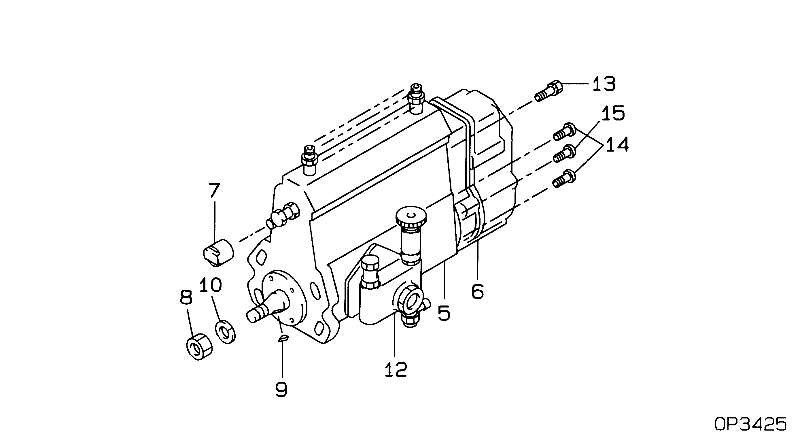
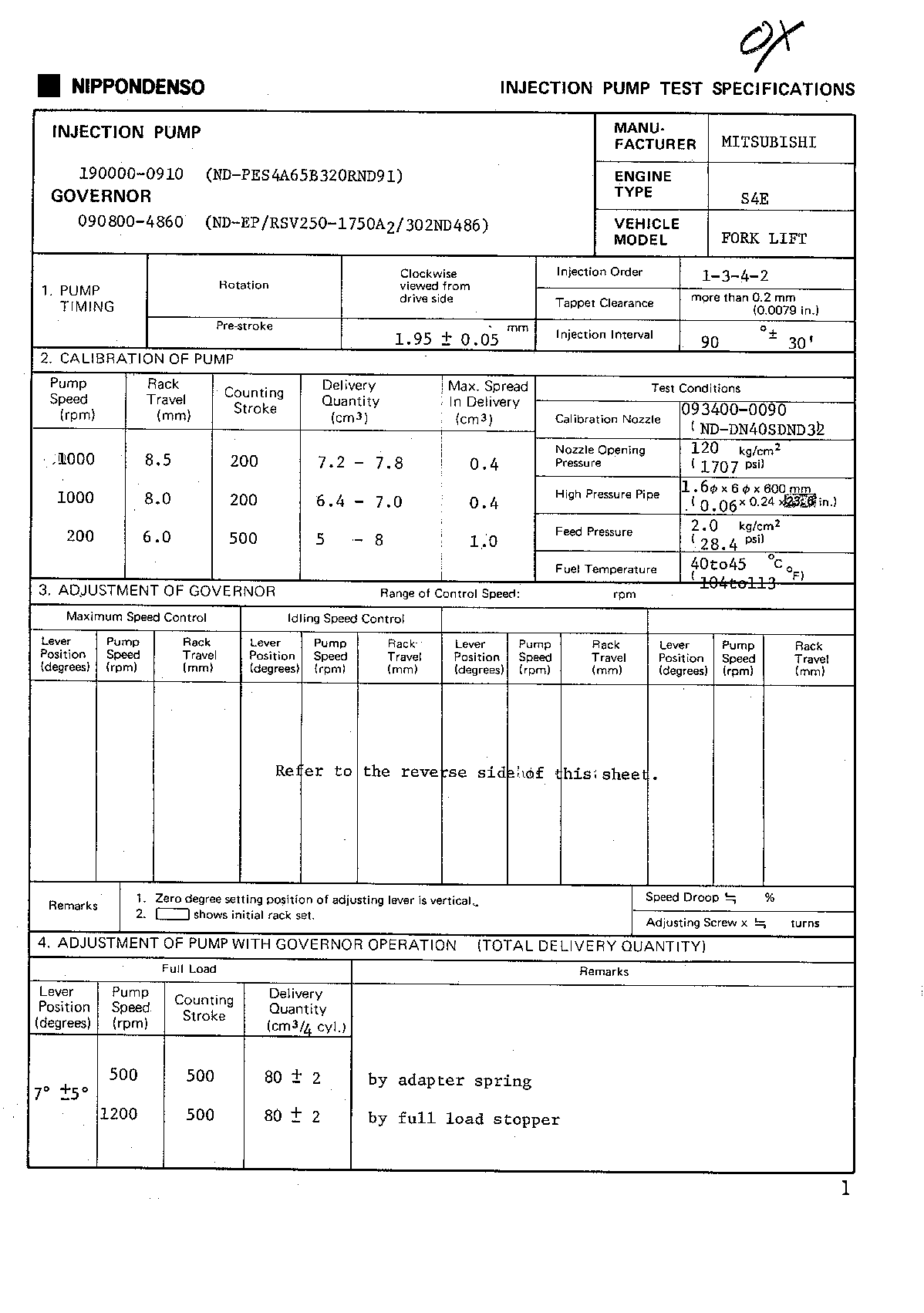
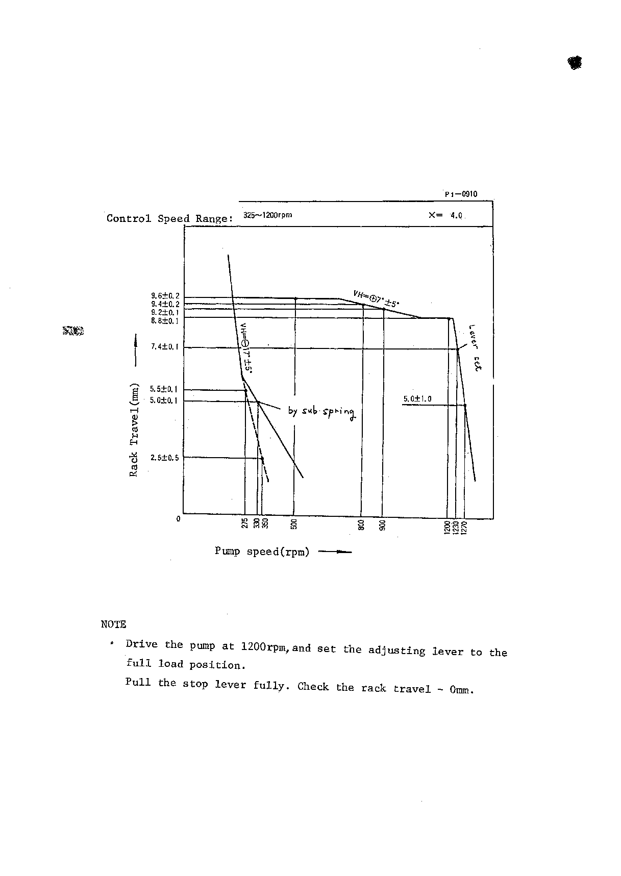
PUMP ASSY, INJECTI
A4,RSV
Include in ##:
19000-00910
as PUMP ASSY, INJECTI
Cross reference number
Part num
Firm num
Firm
Name
19000-00910
PUMP ASSY, INJECTI
Information:
preparatory steps: a) remove timing gear coverb) remove fuel injection pump housing and governorc) remove fuel transfer pump 1. Disconnect the accessory drive oil supply line (1) and the fuel drain line (2). Remove the fuel priming pump.2. Remove the accessory drive shaft gear retaining nut, washer, and sleeve. 3. Using tool (A), remove the accessory drive gear. 4. Remove four retaining bolts (3), two locks and retainer (4).5. Remove the accessory drive housing.6. Remove the accessory drive shaft and bearing as a unit from the housing. 7. Using tool (B), remove bearing (5).Install Accessory Drive Shaft
1. Heat the accessory drive shaft bearing to 300°F (149°C) and install the bearing on the shaft. 2. Install the accessory drive shaft and bearing (1) in the housing.3. Install the accessory drive housing. 4. Install the retainer, locks and retaining bolts.5. Locate top center (TC) compression stroke for No. 1 piston. See LOCATING TOP CENTER COMPRESSION POSITION FOR No. 1 PISTON in TESTING AND ADJUSTING. 6. Rotate the accessory drive shaft until tool (A) can be installed. 7. Install the accessory drive shaft sleeve, drive gear, conical washer and nut. Install the conical washer on the drive shaft with the O.D. in contact with the gear. Tighten the retaining nut (2) to 100 10 lb. ft. (13,8 1,4 mkg).8. Connect the fuel drain line and the oil supply line. Install the fuel priming pump.concluding steps: a) install fuel transfer pumpb) install fuel injection pump housing and governorc) install timing gear cover
1. Heat the accessory drive shaft bearing to 300°F (149°C) and install the bearing on the shaft. 2. Install the accessory drive shaft and bearing (1) in the housing.3. Install the accessory drive housing. 4. Install the retainer, locks and retaining bolts.5. Locate top center (TC) compression stroke for No. 1 piston. See LOCATING TOP CENTER COMPRESSION POSITION FOR No. 1 PISTON in TESTING AND ADJUSTING. 6. Rotate the accessory drive shaft until tool (A) can be installed. 7. Install the accessory drive shaft sleeve, drive gear, conical washer and nut. Install the conical washer on the drive shaft with the O.D. in contact with the gear. Tighten the retaining nut (2) to 100 10 lb. ft. (13,8 1,4 mkg).8. Connect the fuel drain line and the oil supply line. Install the fuel priming pump.concluding steps: a) install fuel transfer pumpb) install fuel injection pump housing and governorc) install timing gear cover