Rating:
Information pump assy, injecti Denso
Components :
Scheme #.#:
№
Qty
Part num
Name
Remarks
Manufacture num
Cross reference number
Part num
Firm num
Firm
Name
19000-00851
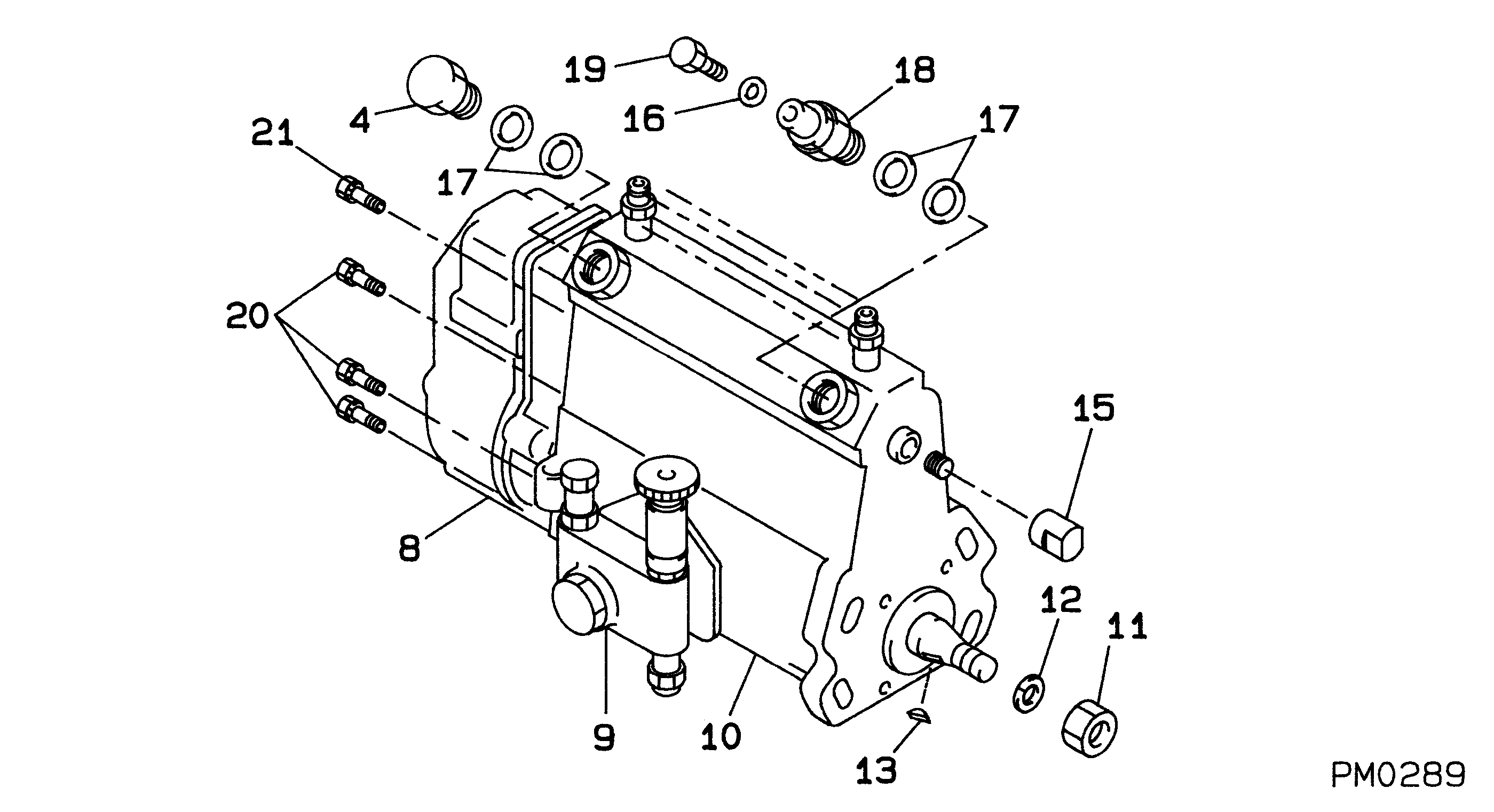
PUMP ASSY, INJECTI
Information:
(1) Remove former fuel injection lines (1), the clamps and through-the-cover fuel line adapters (2) from the engine; these parts will not be needed again. Install 8M4437 Seals on twelve 1W6777 Adapters (3). Put engine oil on the seals and install the adapters in valve cover base assemblies (4) where adapters (2) were removed. Fasten the adapters to bases (4) with two 5N5365 Locks on each and the former nuts. Connect former fuel lines (5) to adapters (3) and the former fuel nozzle adapters. (2) Install a 2W2500 Washer (7) and a 6V6579 Seal (8) on each adapter (3). Install a 5P9267 Seal on each injector pump; put diesel fuel on the seals before installation. Loosely install fuel injection line assemblies: number "6" (9), number "12" (10), number "4" (11), number "2" (12), number "10" (13) and number "8" (14) on the right side of the engine between the fuel injection pumps and adapters (3). See the above chart for the correct part number of the fuel lines. Remove two bolts and install 5N5370 Bracket (15) and 5N5374 Clamp (16) where the bolts were removed. Fasten the fuel injection lines to bracket (15) with two 5N5369 Dampers, a 5N5371 Clamp and two 2W7884 Bolt Assemblies. Fasten the fuel injection lines to clamp (16) with two 5N5373 Dampers, a 5N5372 Clamp and two 2W7884 Bolts. Use 5N5957 and 5N5958 Clamps, two 5N5956 Dampers and a 2W7884 Bolt Assembly to fasten the fuel lines together at (A). Use 5N5376 and 5N5377 Clamps, two 5N5375 Dampers and three 2W7884 Bolt Assemblies to fasten the fuel lines together at (B). Tighten the bolt assemblies to 10 N m (7 lb.ft.) torque. Tighten nuts (17) on each end of the fuel injection lines to 40 7 N m (35 5 lb.ft.) torque, then tighten nuts (18).(3) Loosely install fuel injection line assemblies; number "11" (19), number "3" (20), number "7" (21), number "9" (22), number "5" (23) and number "1" (24) on the left side of the engine between adapters (3) and the fuel injection pump as shown. Remove a bolt and install 5N5370 Bracket (25) where the bolt was removed. Fasten the fuel lines to bracket (25) with two 5N5369 Dampers, a 5N5371 Clamp and two 2W7884 Bolts. On engines equipped with aftercooler, fasten 5N5379 Plate (26) to an existing bolt on the aftercooler. Fasten the fuel injection lines to plate (26) with two 5N5378 Dampers, a 5N5374 Clamp and two 2W7884 Bolt Assemblies. Use two 5N5376 and 5N5377 Clamps, four 5N5375 Dampers and four 2W7884 Bolt Assemblies to fasten the fuel lines together at locations (C). If the engine does not have an aftercooler, use 5N5957 and 5N5958 Clamps, two 5N5956 Dampers and a 2W7884 Bolt Assembly to fasten the fuel injection lines together at (D). Tighten the fuel lines as shown in step 2.2W5100 Fuel Lines Drain Group
(1) Install a 9L8496 Tee (1) in each adapter (2). Connect tees (1) together with ten 5N5940 Tube Assemblies (3).
(1) Install a 9L8496 Tee (1) in each adapter (2). Connect tees (1) together with ten 5N5940 Tube Assemblies (3).