Rating:
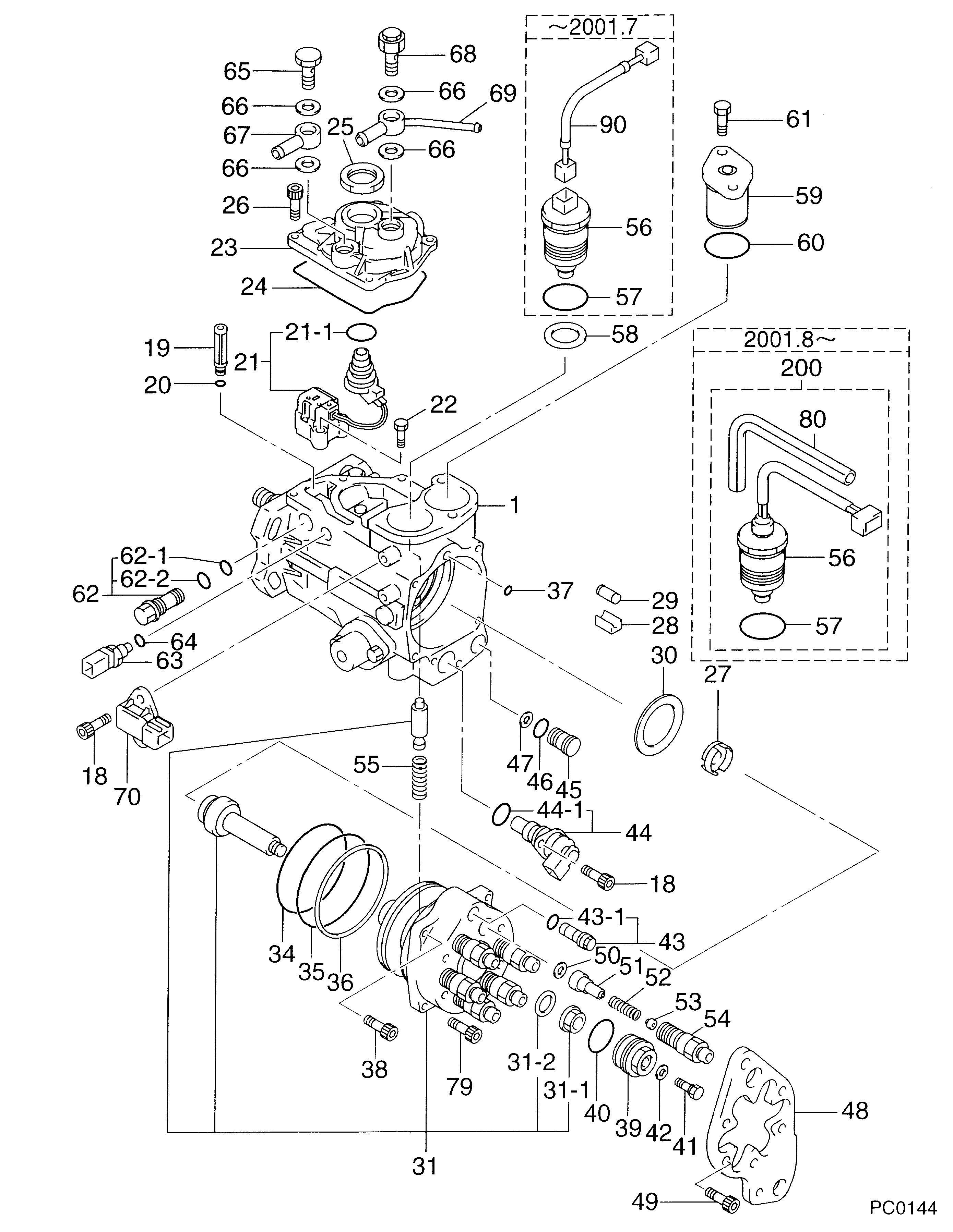
Information pump assy, injecti Denso
Compare Prices: .
As an associate, we earn commssions on qualifying purchases through the links below

Diesel Engine Fuel Injection Pump High Performance Fuel Pump 098000-2010, 098000-2011, 098000-0010,Compatible For 1HD 22100-1C420, 22100-1C170,engine Replacement Parts
YHFWER Increase Fuel Pressure: The main function of an injection pump is to increase the fuel pressure enough to inject into the cylinders of a diesel engine. This high-pressure injection facilitates the thorough atomization and mixing of the fuel, resulting in higher combustion efficiency || Precise control of fuel injection time: The fuel injection pump can precisely control the fuel injection time, ensuring that the fuel is injected at the right time during the diesel engine duty cycle. This contributes to the smooth operation and efficient combustion of the diesel engine || Adjust the amount of fuel injected: According to the load and speed requirements of the diesel engine, the fuel injection pump can adjust the amount of fuel injected. This modulation capability allows diesel engines to maintain optimal performance and fuel economy under different operating conditions || Adapt to different diesel engine models: The design of the fuel injection pump is diversified to adapt to different models and specifications of diesel engines. Whether it's a light vehicle, a commercial vehicle or an industrial diesel engine, there is a corresponding fuel injection pump to choose from || Stable operation: The stability and reliability of the fuel injection pump are essential for the continuous and stable operation of the diesel engine. Constant fuel supply and proper injection, thus avoiding engine failures and downtime
YHFWER Increase Fuel Pressure: The main function of an injection pump is to increase the fuel pressure enough to inject into the cylinders of a diesel engine. This high-pressure injection facilitates the thorough atomization and mixing of the fuel, resulting in higher combustion efficiency || Precise control of fuel injection time: The fuel injection pump can precisely control the fuel injection time, ensuring that the fuel is injected at the right time during the diesel engine duty cycle. This contributes to the smooth operation and efficient combustion of the diesel engine || Adjust the amount of fuel injected: According to the load and speed requirements of the diesel engine, the fuel injection pump can adjust the amount of fuel injected. This modulation capability allows diesel engines to maintain optimal performance and fuel economy under different operating conditions || Adapt to different diesel engine models: The design of the fuel injection pump is diversified to adapt to different models and specifications of diesel engines. Whether it's a light vehicle, a commercial vehicle or an industrial diesel engine, there is a corresponding fuel injection pump to choose from || Stable operation: The stability and reliability of the fuel injection pump are essential for the continuous and stable operation of the diesel engine. Constant fuel supply and proper injection, thus avoiding engine failures and downtime
Components :
Scheme #.#:
№
Qty
Part num
Name
Remarks
Manufacture num
000
[01]
09800-02011
PUMP ASSY, INJECTI
ECD-V4
22100-1C420
TOYOTA
Include in ##:
09800-02011
as PUMP ASSY, INJECTI
Cross reference number
Part num
Firm num
Firm
Name
09800-02011
22100-1C42
PUMP ASSY, INJECTI
Information:
1-Inlet air pipe. 2-Exhaust elbow. 3-Turbocharger oil drain line. 4-Turbocharger oil supply line. 5-Turbocharger. 6-Fuel injection lines (six). 7-Heat shield. 8-Exhaust manifold (three sections).Turbocharger Removal And Installation
Refer to SERVICE GUIDE for Preliminary Information.
1-Exhaust elbow. 2-Turbocharger oil supply line. 3-Bolts and nuts (two each). 4-Bolts, locks and nuts (four each). 5-Turbocharger oil drain line. 6-Inlet air pipe. Apply 9M3710 Anti-Seize Compound to threads of bolts (3 and 4) when installing turbocharger.Turbocharger Disassembly And Assembly
8S9944 Turbine Holder.1,3,5 Remove nut (1). Position the compressor end of housing (5) in an oil bath so only impeller (3) is immersed in oil. Heat impeller to 350° F. (176° C.) for not longer than ten minutes. Remove unit from oil bath and press the shaft and turbine wheel from impeller (3).1,3,5 At installation, heat impeller (3) to a maximum of 350°F. (176°C.) for not longer than ten minutes and proceed as follows: For ease of impeller installation, place the turbine wheel end of center housing (5) in an 8S9944 Turbine Holder.a. Immediately install impeller (3) on shaft, install nut (1) and tighten it to 120 lb. in. (138,4 cm.kg).b. Allow impeller to cool to less than 150°F. (65, 49°C.) and remove nut (1).c. Clean and smooth the washer face of nut (1). Lightly oil the threads of turbine shaft and nut and install the nut.d. Tighten nut (1) to 20 lb. in. (23,0 cm.kg), then tighten an additional 120°.2 Coat threads with 9M3710 Anti-Seize Compound.4,5 Install thrust plate assembly (4) so oil hole aligns with oil hole in housing (5).