Rating:
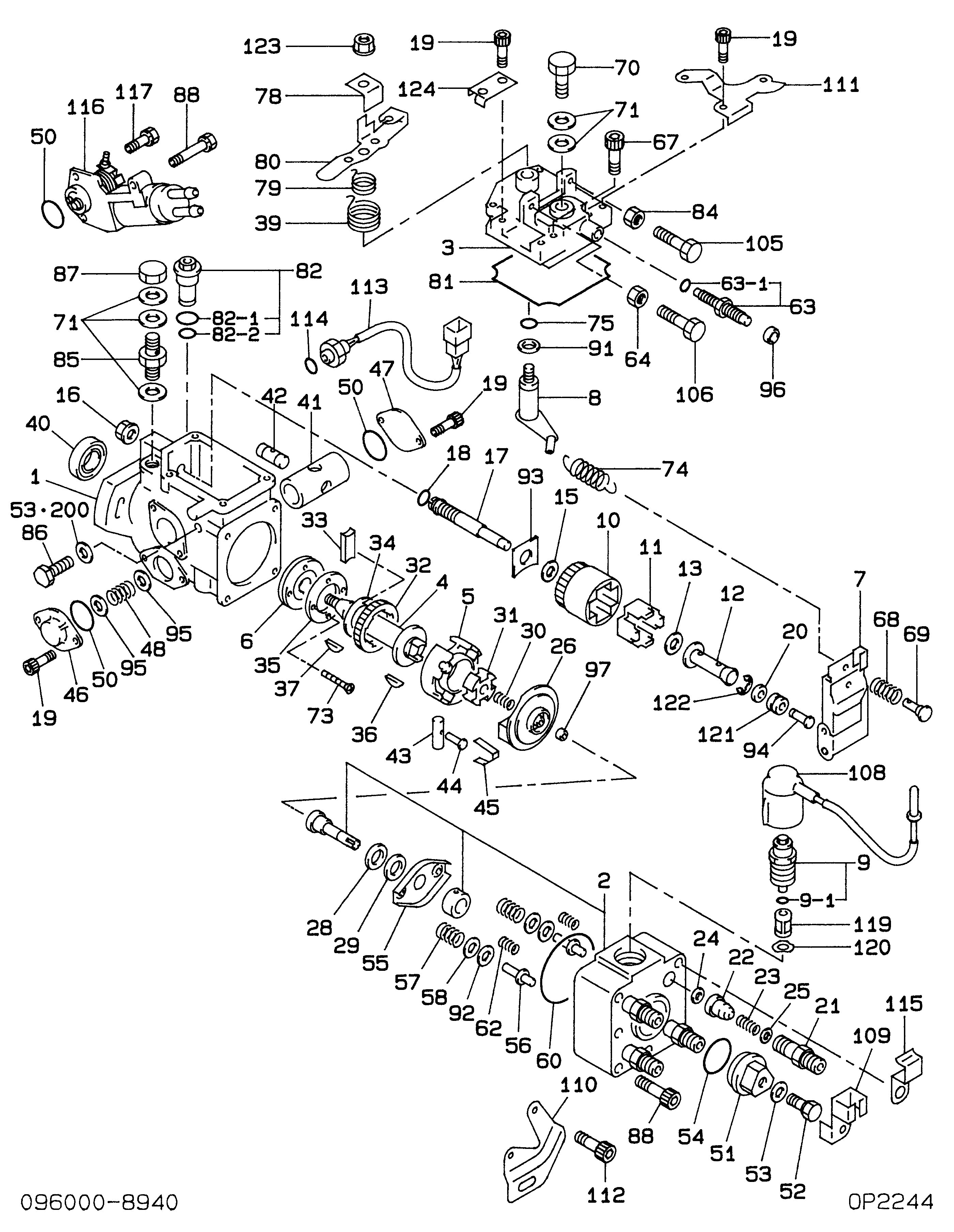
Information pump assy, injecti Denso
Components :
Scheme #.#:
№
Qty
Part num
Name
Remarks
Manufacture num
Cross reference number
Part num
Firm num
Firm
Name
09600-08942
PUMP ASSY, INJECTI
Information:
Prior to stopping an engine that is being operated at low loads, run the engine at low speed for 30 seconds before stopping. If the engine has been operating at high load, then it should be run at low speed for three to five minutes to reduce and stabilize internal engine coolant and oil temperatures before stopping. Avoiding hot engine shutdowns will maximize turbocharger shaft and bearing life. Make sure the Engine Stopping procedure is understood. Follow the engine stopping procedure outlined below to allow the engine to cool. Make sure the Engine Stopping procedure is understood. Refer to the Engine Control, Monitoring and Protection topic for information regarding GSC control panel.The engine may be shutdown in several ways. To manually stop the engine, refer to the following information and instructions. The engine is equipped with an Emergency Stop Push Button (ESPB) and an Engine Control Switch (ECS). The ECS has four positions:* OFF/RESET* AUTO* MAN. START* COOLDOWN STOPTo manually stop the engine the Engine Control Switch (ECS) may be turned to the COOLDOWN STOP, AUTOmatic or OFF/RESET positions.Emergency Stop Procedure
Emergency stop controls are for EMERGENCY use ONLY. DO NOT use Emergency Stop Pushbutton (ESPB) for normal stopping procedure. Do NOT start the engine until the problem necessitating the emergency stop has been located and corrected.
The Emergency Stop Pushbutton is located on the front of the control panel. The Emergency Stop Pushbutton will cause immediate shutoff of fuel and/or air. Emergency shutoff controls (including any auxiliary Emergency Stop inputs) should only be used when an emergency exists, and not used to routinely stop the engine. * Emergency stops may be made through the Emergency Stop Pushbutton (ESPB). If the need for emergency engine shutdown occurs, Push the EMERGENCY STOP Pushbutton located on the control panel. This will activate the air and/or fuel shutoffs.* Reset the EMERGENCY STOP Pushbutton (pull out and rotate the button in the direction indicated on the button). Some EMERGENCY STOP Pushbuttons can be pulled out to reset, not requiring any rotation. Manual Fuel Shutoff Lever
A manual shutdown shaft/lever is provided to override the governor control of the engine. This shutdown will only move the fuel control linkage to the fuel OFF position to starve the engine of fuel. The engine will coast to a stop. Be sure to secure any external system components that have been operating to support the engine operation.Manual Stop Procedure
Follow the engine stopping procedure outlined below, to allow the engine to cool. Make sure the Engine Stopping procedure is clearly understood.1. Open the main electrical circuit breaker to remove the load. Lower engine speed with the Manual Speed Potentiometer (MSP) on the control panel. 2. Check the crankcase oil level while the engine is idling. Maintain the oil level between the ADD and FULL marks on the ENGINE AT LOW IDLE WITH WARM OIL side of the dipstick. 3. Adjust all other control systems that must be regulated prior to engine shutoff (voltage regulator, idle/rated switch, etc.). Reduce engine