Rating:
Information pump assy, injecti Denso
Product
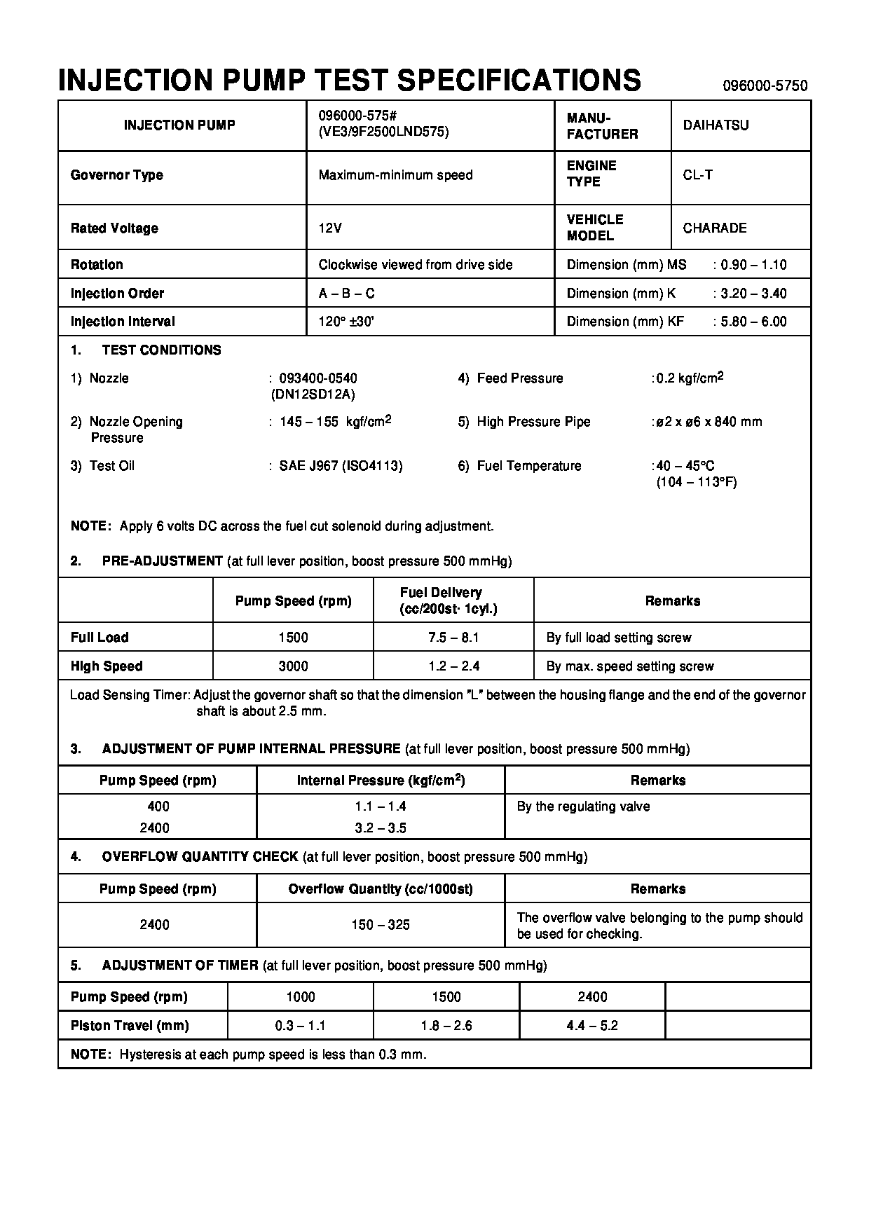
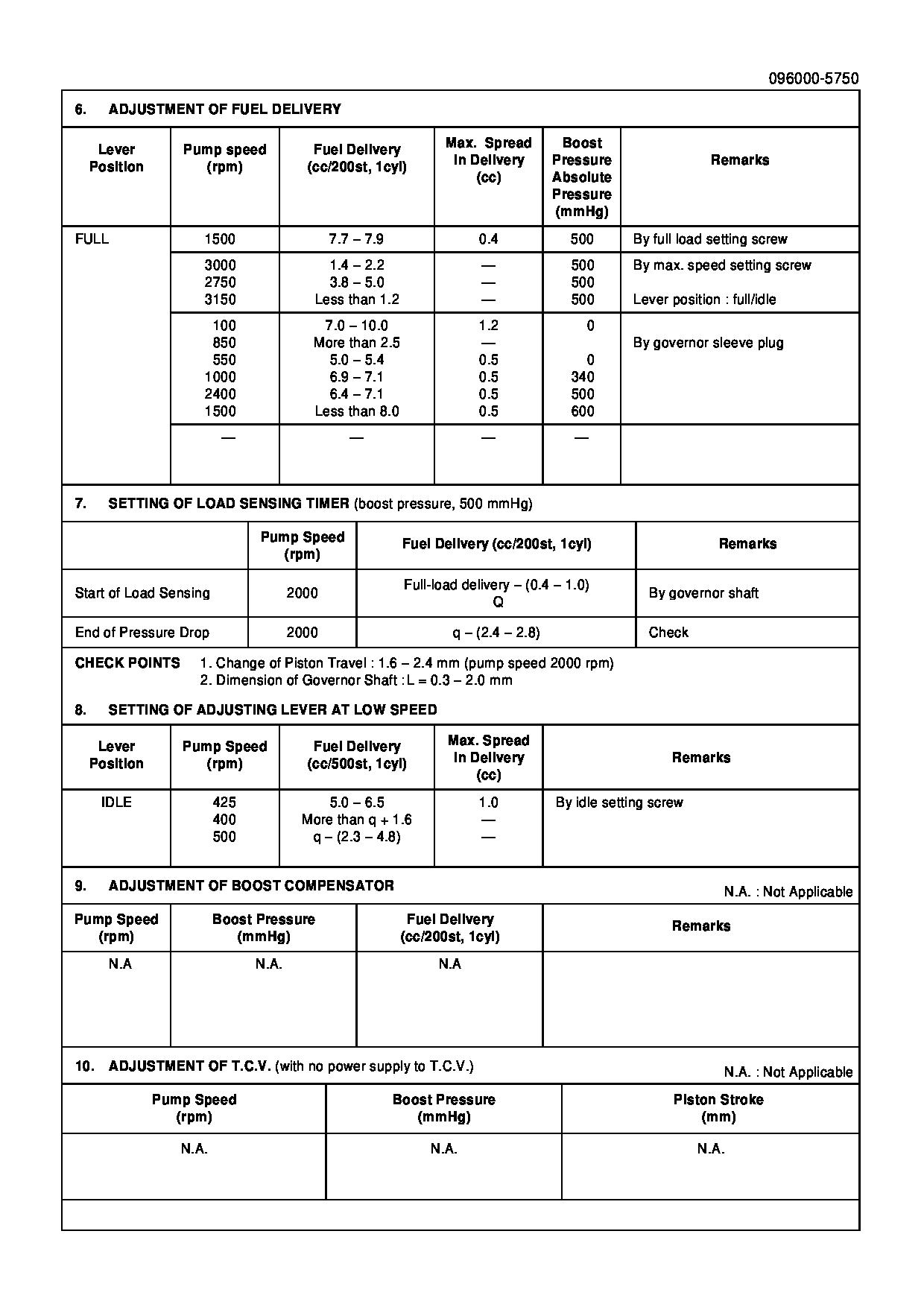
Fuel Injection Pump
Vehicle engine
CHARADE CL-T
Engine
CL-T
Serial start-end
8809--9112
Info
Injector Nozzle
093500-3480
DAIHATSU
PUMP ASSY, INJECTI
GA
- * THE SPARE PARTS OF THE SOLENOID KIT IS 096010-0690
- (INCLUDING O-RINGS).
Injector nozzle:
0935003480
KIT List:
Part name
Kit1
Kit2
Components :
Scheme #.#:

№
Qty
Part num
Name
Remarks
Manufacture num
000
[01]
09600-05750
PUMP ASSY, INJECTI
Include in ##:
09600-05750
as PUMP ASSY, INJECTI
Cross reference number
Part num
Firm num
Firm
Name
09600-05750
DAIHATSU
PUMP ASSY, INJECTI
Information:
Fig. 1-TurbochargerThe turbocharger is located on the left side of the engine as shown in Fig. 1.For theory of turbocharger operation, refer to FOS Manual-ENGINES.Removal
Stop engine and allow exhaust system time to cool.Remove engine enclosers until turbocharger is accessible.
Fig. 2-Turbocharger RemovalDisconnect the air intake hose (1, Fig. 2) at turbocharger.Remove exhaust elbow (2) and adapter (3).Disconnect the inlet oil line (4) and return oil line (5) at turbocharger.Remove the turbocharger mounting flange stud nuts (6). Loosen, but do not remove, compressor housing cap screws (7).Lift turbocharger off exhaust manifold, and disengage turbocharger and coupling (8) from intake manifold.Cover all openings and clean exterior of turbocharger with a pressure spray of cleaning solvent. Dry turbocharger.Testing
Radial Bearing Movement
Fig. 3-Radial Bearing Movement CheckFasten a plunger dial indicator to the turbocharger housing mounting flange as shown in Fig. 3.Apply side pressure on the turbine shaft back and forth, equal pressures should be applied simultaneously (Fig. 3).The total movement should be 0.003 to 0.006 in. (.08 to 0.15 mm).Axial Bearing Movement (Bearing End Play)
Remove compressor housing-to-center housing cap screws (7, Fig. 6), lock plates (6) and clamps (5).
Fig. 4-Axial Bearing Movement CheckFasten dial indicator to turbine housing so that the indicator tip rests on the end of the shaft (Fig. 4).Move the shaft back and forth axially by hand. The total axial movement of the shaft should be 0.001 to 0.004 in. (0.03 to 0.10 mm). If not repair or replace unit.Repair
As each part is removed, place it in a clean protective container.Refer to Fig. 6 for part identification and relationship.
Fig. 5-Turbine Housing RemovalScribe a line on the mating surfaces of the turbine housing (1, Fig. 5) and center housing (2) to aid in alignment during reassembly.Remove the turbine housing-to-center housing cap screws (5, Fig. 5), lock plates (3), and clamps (4). Carefully remove turbine housing.
Fig. 6-Turbocharger Exploded View
Fig. 7-Removing Compressor (Impeller)Mount a suitable holding fixture (1, Fig. 7) (see Group 0499 Special Tools - Turbocharger) in a vise.Insert the turbine wheel into the fixture.Use a double universal socket to remove the compressor wheel retaining nut to avoid possible bending of the shaft.Remove the impeller (2, Fig. 7) from the shaft.
Fig. 8-Shaft and Wheel AssemblyRemove the turbine wheel and shaft assembly (3, Fig. 8) from the center housing keeping it centered until it is clear of the housing. Fig. 8 shows the turbine wheel assembly (1). The piston ring (2) can now be removed.Remove the back plate to center housing cap screw (16, Fig. 6) and lock plates (15).Carefully remove back plate by tapping with a soft mallet.
Fig. 9-Back Plate Assembly IMPORTANT: Back plate (2, Fig. 9) and the spring (1) are sold only as an assembly. The installed depth of the spring is a controlled dimension. Therefore, do not remove or replace the spring by itself. Cleaning can be done without removing the spring from the back plate.
Fig. 10-Removing Thrust Collar and Thrust WasherRemove the thrust collar (2, Fig. 10) and thrust washer (3) as shown in Fig. 10. Remove the O-ring