Rating:
Information pump assy, injecti Denso
Product
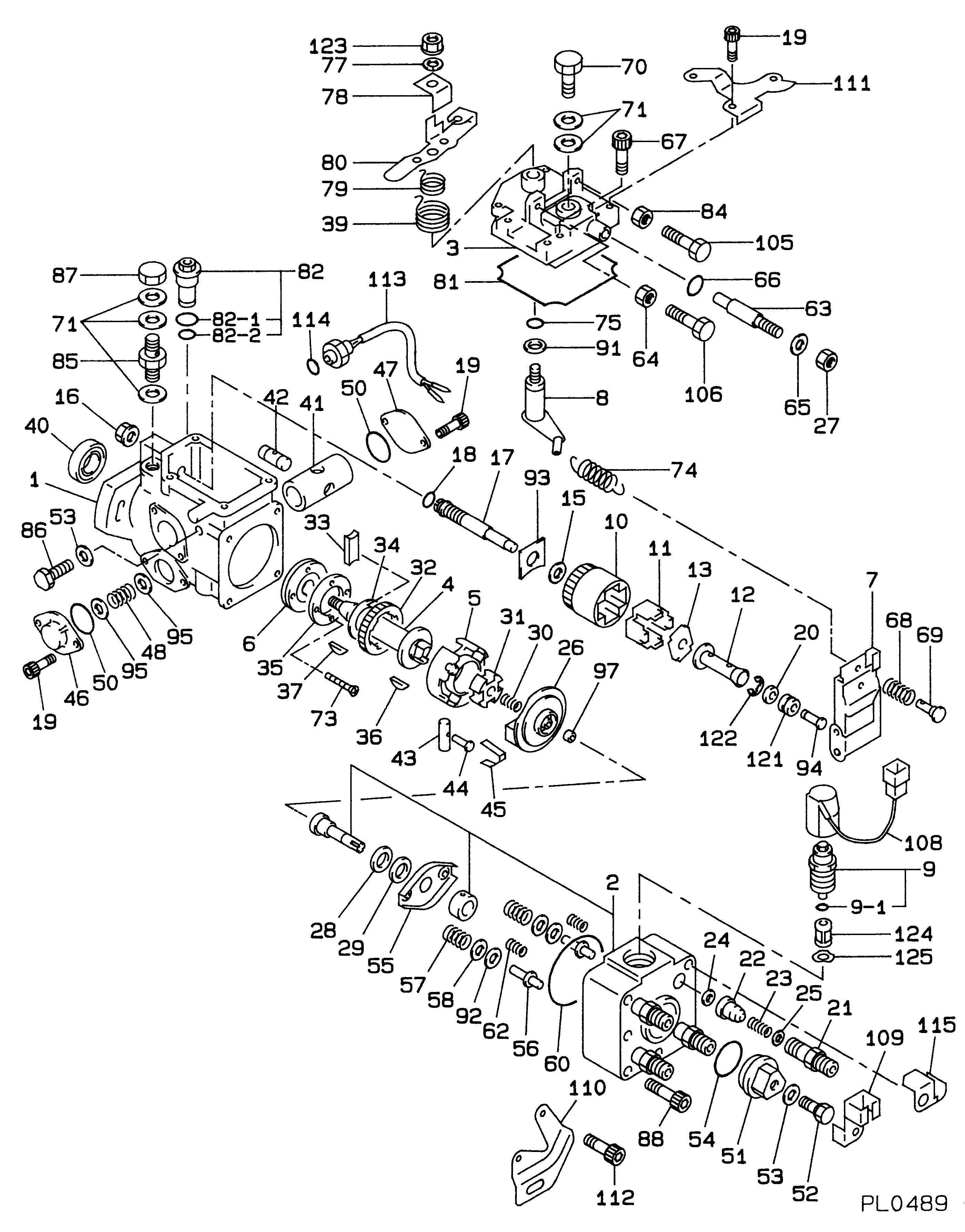
Fuel Injection Pump
Vehicle engine
INDUSTRIAL DL
Engine
DL
Serial start-end
8801-
Info
Injector Nozzle
093500-3800
Injector nozzle:
0935003800
KIT List:
Part name
Kit1
Kit2
Components :
Scheme #.#:
№
Qty
Part num
Name
Remarks
Manufacture num
000
[01]
09600-05020
PUMP ASSY, INJECTI
-9508
Include in ##:
09600-05020
as PUMP ASSY, INJECTI
Cross reference number
Part num
Firm num
Firm
Name
09600-05020
PUMP ASSY, INJECTI
Information:
120G And 130G Motor Graders
Governor Linkage Adjustment
(1) Rod. (2) Nut. (3) Control lever. (4) Lever. (5) Pin. (6) High idle stop. (7) Locknut. (8) Low idle stop. (9) Locknut. (10) Decelerator treadle. (11) Floor plate. (12) Accelerator treadle. (13) Lever. (14) Rod. (15) Locknut. (16) Lever. (17) Locknut. (A) 9.7 mm (.38 in). (B) 4.8 mm (.19 in). (C) 38.1 mm (1.50 in). (D) 60.5 3.0 mm (2.38 .12 in). DO NOT USE control lever (3), or decelerator treadle (10) to shut OFF the engine.To shut engine OFF, pull up on accelerator treadle (12).1. Tighten nut (2) just enough so position of control lever (3) is not affected by the operation of the accelerator treadle (12) and decelerator treadle (10).2. With the parking brake ON and engine stopped, BE SURE disconnect switch is OFF.3. Remove pin (5).4. Loosen LOW IDLE stop (8) and HIGH IDLE stop (6) so they do not touch lever (13).5. Move control lever (3) to LOW IDLE position.6. Turn LOW IDLE stop (8) until it touches lever (13) and tighten locknut (9).7. Adjust length of rod (14) so distance from top of lever (16) to bottom of floor plate (11) is (C) 38.1 mm (1.50 in) as shown.8. Loosen locknut (15) and adjust length of rod so top of decelerator treadle (10) is (B) 4.8 mm (.19 in) above floor plate (11) as shown. If machine is equipped with a thick floor insulation pad, (used with enclosed cab), adjust decelerator treadle (10) so top of treadle is (A) 9.7 mm (.38 in) above top of floor plate and tighten locknut (15).9. Move control lever (3) to HIGH IDLE position.10. Turn HIGH IDLE stop (6) until it touches lever (13) and tighten locknut (7).11. Loosen locknut (17) and adjust accelerator treadle (12) so that distance from bottom of plate on treadle to top of floor plate (11) is (D) 60.5 3.0 mm (2.38 .12 in) as shown.12. Move lever (4) to HIGH IDLE position and adjust length of rod (1) so pin (5) can be installed.13. Install pin (5).
DO NOT adjust the linkage so the treadle can be used to shut off the engine. If the operator is in a standing position and places a foot on the treadle, the engine could be unexpectedly shut off, creating a situation where the machine can be difficult to control.
518 Skidder
1. Move governor shaft (3) to SHUT OFF position and install lever (2) on shaft (3) at angle (A).2. Adjust length of rod (5) so stop (4) on pedal (1) is at dimension (B) from the floor plate.Angle (A) ... 35 5°Dimension (B) ... 67 1 mm (2.64 .01 in)3. Tighten nut (6) ... 12 4 N m (9 3 lb ft)D5H
1. Move governor lever (2) to high idle and install spring (6). Move governor lever (2) to vertical position and adjust stop bolt (3) to contact lever (2), back off one turn and lock.2. Position lever (9) on