Rating:
Information pump assy, injecti Denso
Product
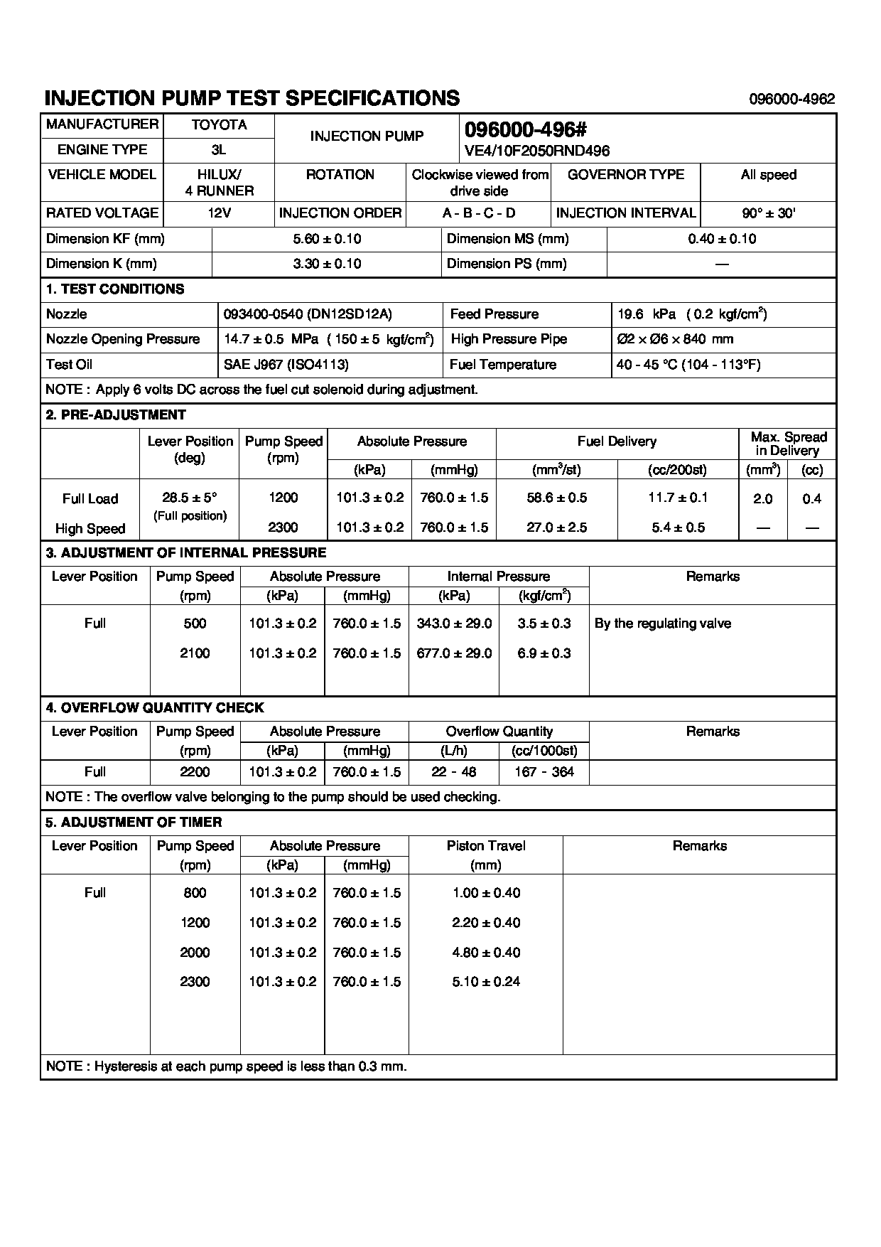
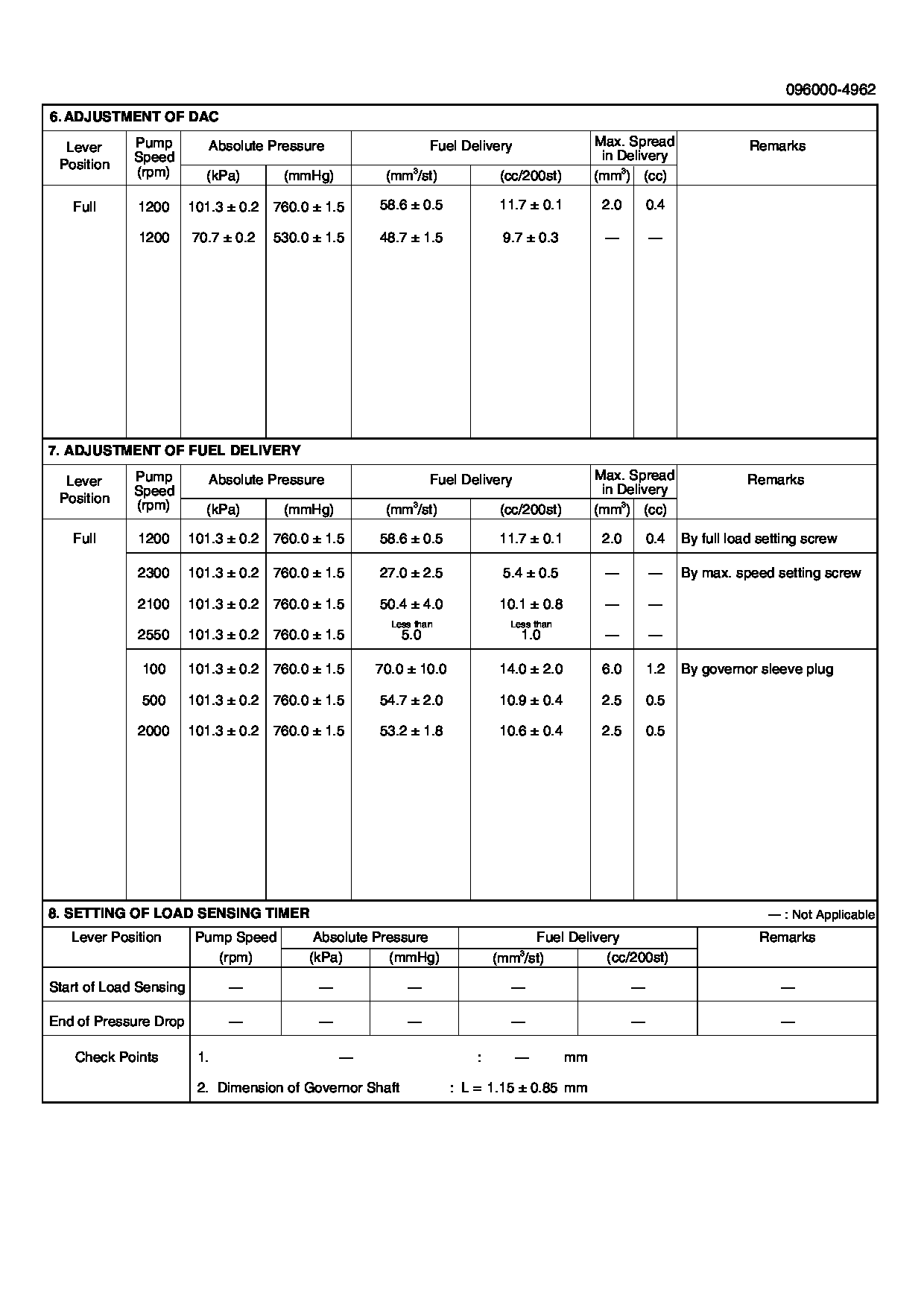
Fuel Injection Pump
Vehicle engine
HILUX 3L
Engine
3L
Serial start-end
8804-
Info
Injector Nozzle
093500-4180
Manufacture:
22100-54880 TOYOTA
Dim 1
3.2-3.4
Dim 2
5.8-6.0
Dim 3
0.3-0.5
Dim 4
Dim 5
Dim 6
Information
THE CONNECTING PORTION BETWEEN COUPLING AND DRIVESHAFT END HAS BEEN MODIFIED SINCE JULY, 2000.A COUPLING SPACER IS ADOPTED INSTEAD OF SPRING. KF DIMENSION IS 5.5-5.7MM AFTER THE MODIFICATION.
Injector nozzle:
0935004180
KIT List:
Part name
Kit1
Kit2
Cross reference number
Part num
Firm num
Firm
Name
0960004960
22100-54880
TOYOTA
PUMP ASSY, INJECTI
Test Calibration Data:
0960004960
22100-54880


0960004961
22100-54880


0960004962
22100-54880
Information:
start by:a) remove fuel injection lines**This operation location is in the ENGINE DISASSEMBLY AND ASSEMBLY section. 1. Disconnect the fuel lines from fuel transfer pump (4) and fuel manifold (3). Disconnect fuel line (2) from the fitting. Disconnect the fuel return line to the tank at (1). Install plugs or caps on all fuel line openings.2. Disconnect drain line (5) from the governor housing. Move the fuel lines and drain line clear of the fuel injection pump housing and governor. 3. Remove bolts (6) that hold the oil manifold to the governor housing. 4. Remove cover (7) from the timing gear cover.5. Remove the bolt and washer that hold the timing gear to the camshaft in the fuel injection pump housing. 6. Install tooling (A) and loosen the timing gear on the camshaft in the fuel injection pump housing.7. Fasten a strap and hoist to the fuel injection pump housing and governor as shown. 8. Remove three nuts (8) and remove the fuel injection pump housing and governor. Weight is 25 kg (56 lb.).Install Fuel Injection Pump Housing And Governor
1. Be sure O-ring seals (1) and (2) are in position on the fuel injection pump housing and governor and put clean oil on the O-ring seals.2. Remove the cover on the fuel injection pump housing and install timing pin (A). Turn the camshaft until timing pin (A) goes in the groove in the camshaft as shown. 3. Fasten a strap and hoist to the fuel injection pump housing and governor and put in position on the timing gear plate and oil manifold (3). Install the three nuts that hold the fuel injection pump housing to the timing gear plate and the two bolts that hold the governor housing to oil manifold (3).
After the fuel injection pump housing and governor are installed on the timing gear plate be sure the rack is free to move. The O-ring seal on the drive end of the fuel injection pump can hold the rack and prevent free movement of the rack. If the rack does not move freely remove the fuel injection pump housing and governor and check the O-ring seal on the drive end of the fuel injection pump housing.
4. Install the bolt and washer (4) as shown to hold the timing gear to the camshaft. Install washer (4) with the larger outside diameter toward the bolt head. Tighten the bolt finger tight only.5. Use the following procedure to put the No. 1 piston at top center on the compression stroke. No. 1 piston at top center (TC) on the compression stroke is the starting point for all timing procedures. The engine is seen from the flywheel end when direction of flywheel rotation is given. Do not turn the flywheel backward. a) Remove plug (5) from the flywheel housing and the breather from the valve cover.b) Turn the flywheel counterclockwise until a 3/8"-16 NC bolt (6) at least 2.5 in. long can be installed in the flywheel through the hole in