Rating:
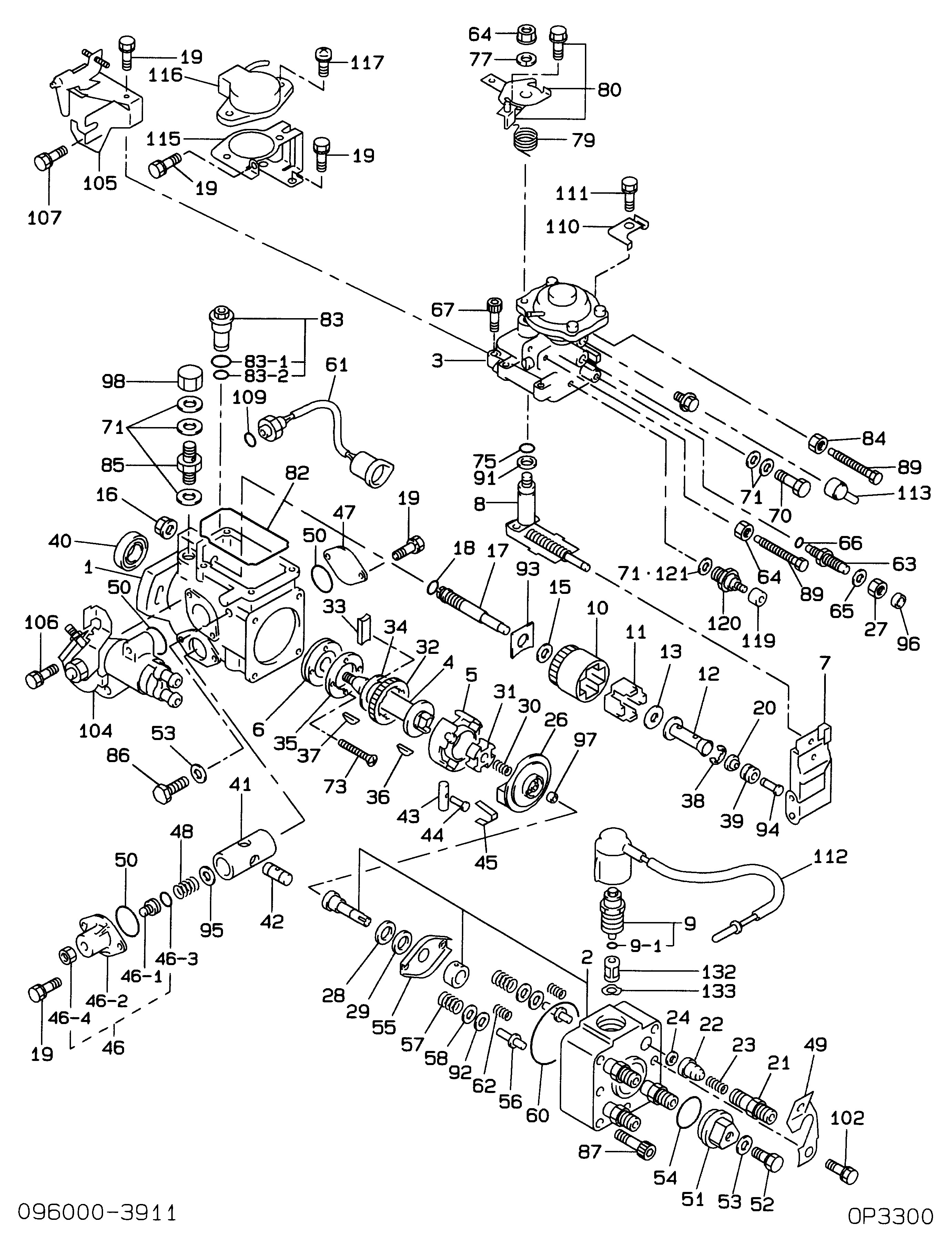
Information pump assy, injecti Denso
Components :
Scheme #.#:
№
Qty
Part num
Name
Remarks
Manufacture num
000
[01]
09600-03911
PUMP ASSY, INJECTI
22100-54690
TOYOTA
Include in ##:
09600-03911
as PUMP ASSY, INJECTI
Cross reference number
Part num
Firm num
Firm
Name
09600-03911
22100-5469
PUMP ASSY, INJECTI
Information:
Introduction
This Special Instruction is intended for the installation of the 257-4183 Unit Injector Wiring Gp Harness Kit for Injector Kits 20R-6731, 20R-6732, 20R-6733, 20R-6734. Do not perform any procedure in this Special Instruction until you have read the information and you understand the information.Important Safety Information
Work safely. Most accidents that involve product operation, maintenance, and repair are caused by failure to observe basic safety rules or precautions. An accident can often be avoided by recognizing potentially hazardous situations before an accident occurs.A person must be alert to potential hazards. This person should also have the necessary training, skills, and tools to perform these functions properly.Safety precautions and warnings are provided in this instruction and on the product. If these hazard warnings are not heeded, bodily injury or death could occur to you or to other persons. Caterpillar cannot anticipate every possible circumstance that might involve a potential hazard.Therefore, the warnings in this publication and the warnings that are on the product are not all inclusive. If a tool, a procedure, a work method, or operating technique that is not specifically recommended by Caterpillar is used, ensure that it is safe for you and for other people to use.
Do not operate or work on this machine unless you have read and understand the instructions and warnings in the Operation and Maintenance Manual. Failure to follow the instructions or heed the warnings could result in injury or death. Contact your Caterpillar dealer for replacement manuals. Proper care is your responsibility.
Personal injury or death can result from improper assembly procedures.Do not attempt any assembly until you have read and understand the assembly instructions.
Accidental engine starting can cause injury or death to personnel working on the equipment.To avoid accidental engine starting, disconnect the battery cable from the negative (−) battery terminal. Completely tape all metal surfaces of the disconnected battery cable end in order to prevent contact with other metal surfaces which could activate the engine electrical system.Place a Do Not Operate tag at the Start/Stop switch location to inform personnel that the equipment is being worked on.
Required Parts
Table 1
Required Tools
Tool Part Number Part Name Qty
A 9S-9150 Terminal Crimp Tool As 1
B 9U-6070 Heat Gun Gp 1 Removal of a Connector from the Wire Harness
The following steps can be used to remove a connector for an injector on the wire harness.
Identify the connectors that need to be replaced. Wiring for the injector solenoid is not sensitive to polarity.
Illustration 1 g06093848
Connectors that are cut from the wire harness
Each injector will have two connectors. The wire on one connector will be longer than the other. Wire (A) is identified as the longer wire and wire (B) is identified as the shorter wire.
Cut wire (2) at a distance of 50 mm (1.9 inch) from the rear surface of the connector.
Cut wire (1) at a distance of 5 mm (0.2 inch) from the cut made on wire (2).
Illustration 2 g01111314
Wire from the harness for side (B) on the connector.
Wire from the harness for side