Rating:
Information pump assy, injecti Denso
Product
Fuel Injection Pump
Vehicle engine
INDUSTRIAL E3112WB
Engine
E3112WB
Serial start-end
0801-
Info
Injector Nozzle
093500-6670
Injector nozzle:
0935006670
Components :
Scheme #.#:
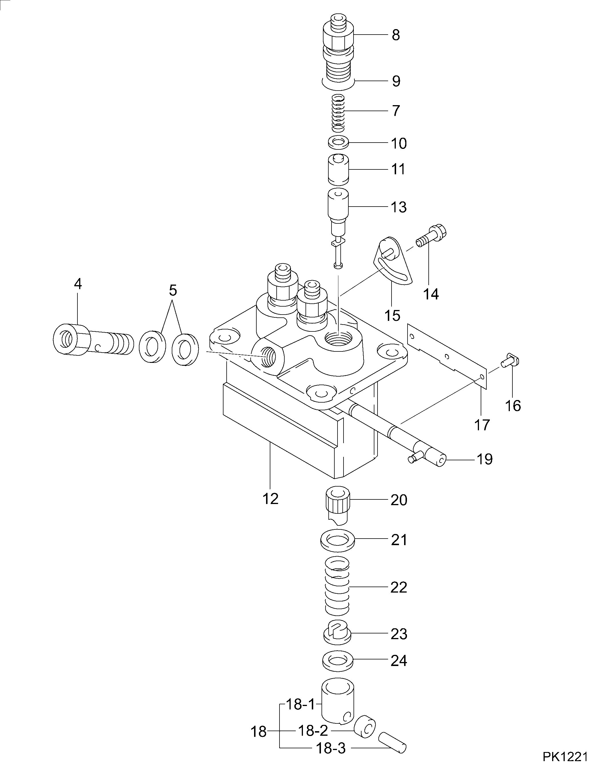
№
Qty
Part num
Name
Remarks
Manufacture num
000
[01]
09450-08690
PUMP ASSY, INJECTI
PFR3M
Include in ##:
09450-08690
as PUMP ASSY, INJECTI
Cross reference number
Part num
Firm num
Firm
Name
09450-08690
PUMP ASSY, INJECTI


Information:
CAMSHAFT LOBE
A. Lobe lift. B. Lobe height. C. Base circle.With camshaft installed in the cylinder block, check end play. End play with new components should be .007 .003 in. (0.18 0.08 mm). The maximum permissible end play is .020 in. (0.51 mm).Camshaft Followers
Use an 8S2293 Magnet to remove the cam followers.
REMOVING CAM FOLLOWERSCam followers establish a wear pattern with the camshaft lobes. Identify and reinstall the followers in the same location from which they were removed. Dishing or circular wear pattern is allowed on the cam follower face, providing the wear face keeps a polished appearance. Replace the follower if the wear face is rough or shows signs of scuffing. A new follower can be used with an old camshaft, providing the lobe is in good condition. Put engine oil on the cam followers and the camshaft lobes before installing the cam followers. Use new cam followers with a new camshaft.Camshaft Gears
1100 and 3100 Engines With Fuel Pump Camshaft Mounted Timing Advance
1. Use a 1P2320 Puller to remove the camshaft small outer gear.
PULLING SMALL GEAR (Typical Example)2. Remove the spacer immediately behind the gear.3. Use a 1P2321 Puller to remove the camshaft large inner gear.
PULLING LARGE GEAR (Typical Example)4. To install, heat both gears to a maximum temperature of 600° F. (315° C).5. Align keyway of large gear with key in camshaft. Install large inner gear on camshaft with timing mark on gear aligned with timing mark on crankshaft gear.6. Install the spacer and small outer gear.
Do not drive gears onto camshaft. Serious damage can result to camshaft or camshaft thrust pin.
Engines With Engine Camshaft Mounted Timing Advance
1. Remove screw (1) and washer (2) from end of camshaft.
REMOVING TIMING ADVANCE RETAINING SCREW
1. Screw. 2. Washer.2. Remove timing advance unit from the camshaft.3. Install puller (A), with spacer (C) over the shaft in the camshaft and spacer (B) on spacer (C) as shown and remove the gear from the camshaft.
REMOVING GEAR (Typical Example)
A. 1P2321 Puller. B. 8S5579 Spacer. C. 9S9155 Spacer.To install the gear use the following procedure:1. Heat the gear to a temperature of approximately 400° F (204° C) before installing on the camshaft.
Do not heat the gear with a torch. Do not heat the gear to a temperature of more than 600° F (315° C). Heating the gear with a torch or to a temperature of more than 600° F (315° C) may cause the two drive dowels for the automatic timing advance to loosen and come out of the gear.
2. Align slot in gear hub with the pin in the camshaft. Install the gear on the camshaft with timing mark on gear aligned with timing mark on crankshaft gear. Be sure the gear is completely seated against the shoulder of the camshaft.
Do not drive the gear on the camshaft.
3. Align holes in weights with dowels in gear and install the automatic timing advance.4. Align pin (3) in washer with hole (4) in camshaft and install washer (2).5. Install screw (1) and tighten to 108