Rating:
Information pump assy, injecti Denso
Product
Fuel Injection Pump
Vehicle engine
INDUSTRIAL V2403-M-T3-EU3
Engine
V2403-M-T3-EU3
Serial start-end
0706-
Info
Injector Nozzle
093500-5070
Injector nozzle:
0935005070
Components :
Scheme #.#:
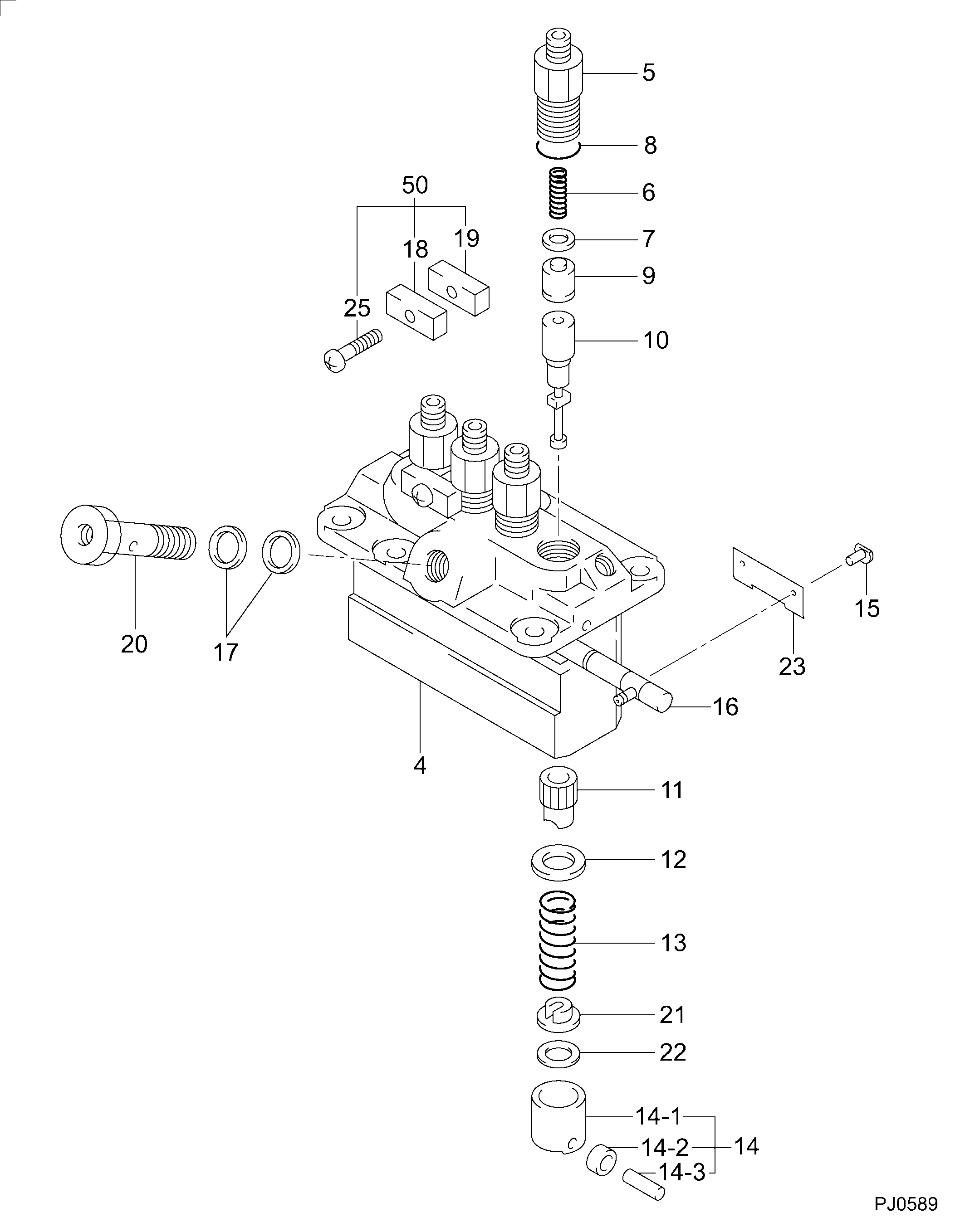
№
Qty
Part num
Name
Remarks
Manufacture num
000
[01]
09450-08670
PUMP ASSY, INJECTI
PFR4M
1J854-51011
KUBOTA
Include in ##:
09450-08670
as PUMP ASSY, INJECTI
Cross reference number
Part num
Firm num
Firm
Name
09450-08670
1J854-5101
PUMP ASSY, INJECTI
0945008670
1J854-51011
KUBOTA
PUMP ASSY, INJECTI

Information:
3. Remove the main bearing caps (1). 4. Remove the crankshaft-weight 200 lbs. (91 kg).5. Remove the crankshaft main bearings from the cylinder block and main bearing caps.
If the main bearings are not going to be replaced mark them with respect to their location in the engine.
6. Using tool setup (A), remove the crankshaft gear and oil seal wear sleeve.Install Crankshaft
1. Heat the crankshaft gear and the oil seal wear sleeve, maximum 600°F (316°C), and install them on the crankshaft.2. Clean the bearing seating surfaces in the cylinder block and the main bearing caps. Install the upper and lower halves of the bearings in the cylinder block bearing caps. Lubricate the bearings with clean SAE 30 engine oil.
If the main bearings are not being replaced the original bearings must be installed in the same location they were removed from.
3. Attach a hoist and position the crankshaft in the cylinder block with the timing marks (1) aligned. 4. Using wire (A), check the main bearing clearance. Install the caps in the respective positions with the number stamped on cap facing the corresponding number cast on side of the cylinder block web. 5. Lubricate the threads of bearing cap retaining bolts and face of washers with clean SAE 30 engine oil. Install the retaining bolts and washers. Tighten both bolts to 30 3 lb. ft. (4,1 0,4 mkg). Mark both bolt heads and bearing caps then tighten each bolt an additional 90° from mark. Remove bearing caps and measure thickness of wire (A). Main bearing clearance should be .0030-.0059 in. (0,076-0,150 mm).6. Lubricate the lower halves of main bearings with clean SAE 30 engine oil. Install main bearing caps in their respective positions. Install cap retaining bolts and washers. Tighten both bolts to 30 3 lb. ft. (4,1 0,4 mkg). Mark both bolt heads and bearing caps then tighten each bolt an additional 90° from mark. 7. Using tool setup (B), check the crankshaft end play as controlled by thrust bearing (2) on rear main bearing. End play should be .0025-.0145 in. (0,064-0,368 mm). Maximum permissible end play is .025 in. (0,64 mm).concluding steps: a) install pistonsb) install timing gear coverc) install flywheel housingd) check fuel injection pump timing. See REMOVE AND INSTALL FUEL INJECTION PUMP HOUSING AND GOVERNOR AS A UNIT.