Rating:
Information pump assy, injecti Denso
Product
Fuel Injection Pump
Vehicle engine
INDUSTRIAL D1703-M-E3BB-1
Engine
D1703-M-E3BB-1
Serial start-end
0701-
Info
Injector Nozzle
093500-4540
Injector nozzle:
0935004540
Components :
Scheme #.#:
№
Qty
Part num
Name
Remarks
Manufacture num
000
[01]
09450-08540
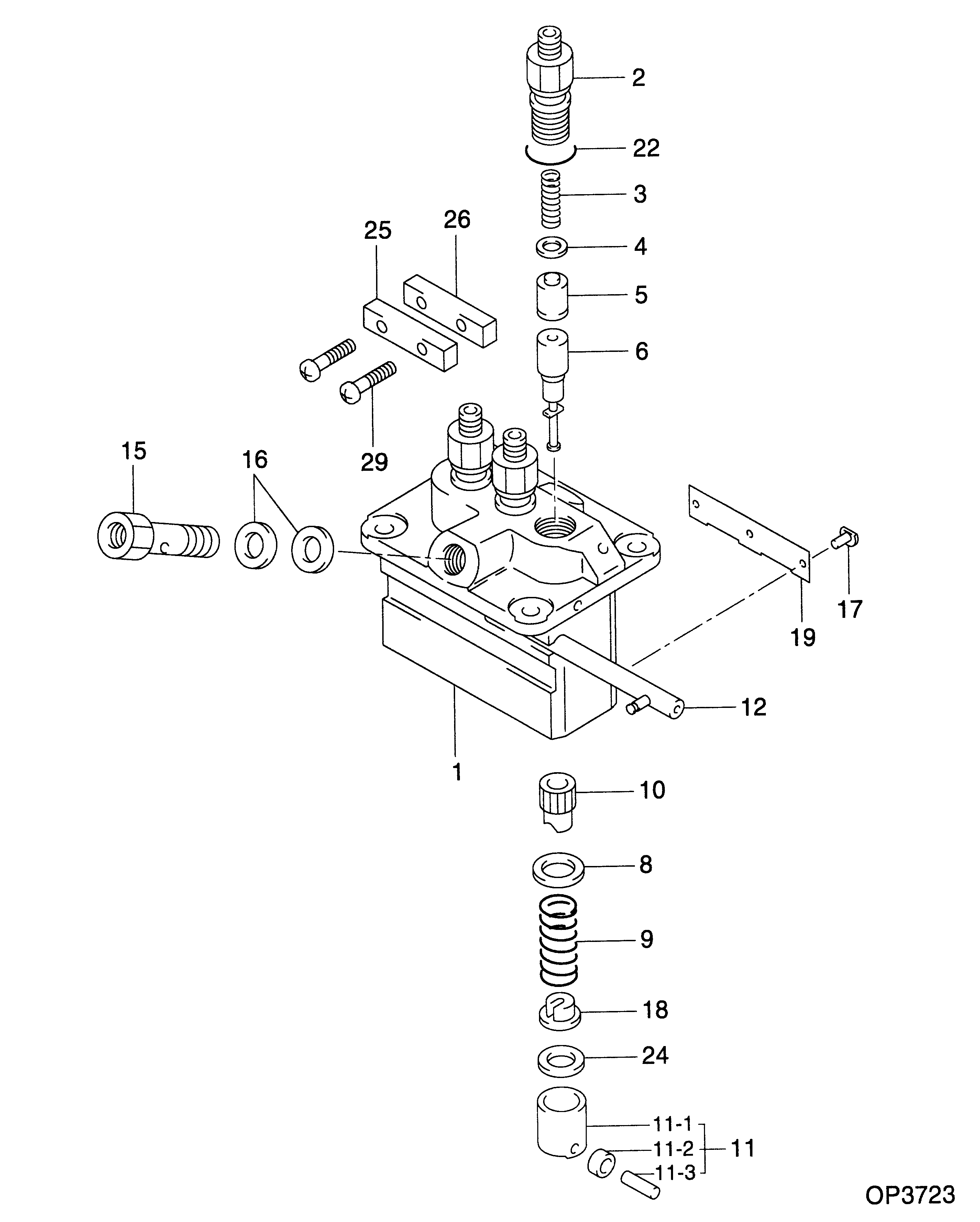
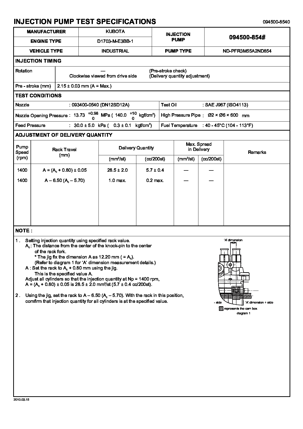
PUMP ASSY, INJECTI
PFR3M
1G711-51011
KUBOTA
Include in ##:
09450-08540
as PUMP ASSY, INJECTI
Cross reference number
Part num
Firm num
Firm
Name
09450-08540
1G711-5101
PUMP ASSY, INJECTI
0945008540
1G711-51011
KUBOTA
PUMP ASSY, INJECTI

Information:
REMOVING COVER
1. Cover.3. Remove screw (2) from rack stop collar (3).
REMOVING SCREW
2. Screw. 3. Rack stop collar.
REMOVING RACK STOP COLLAR
3. Rack stop collar. 4. Spring. 5. Collar.4. Remove rack stop collar (3), spring (4), and collar (5).5. Remove high idle screw (7), bolts (6), and the torque spring. Use wire to fasten the torque spring components together.
HIGH IDLE SCREW
6. Bolts (two). 7. High idle screw.6. Remove the governor housing-to-adapter assembly retaining bolts (8).
GOVERNOR HOUSING RETAINING BOLTS
8. Retaining bolts.
GOVERNOR HOUSING
9. Governor housing. 10. High idle spring.7. Remove governor housing (9) and high idle spring (10).8. Remove the governor spring assembly (11).
REMOVING GOVERNOR SPRING ASSEMBLY
11. Governor spring assembly.9. Remove the bolts (12) and lock (14) from the cylinder and weight assembly (13).
CYLINDER AND WEIGHT ASSEMBLY
12. Bolts. 13. Cylinder and weight assembly. 14. Lock.10. Remove the cylinder and weight assembly (13).
REMOVING CYLINDER AND WEIGHT ASSEMBLY
13. Cylinder and weight assembly.11. Remove piston (15) and spring (16).
REMOVING PISTON
15. Piston. 16. Spring. 17. Bolts.12. Remove the adapter assembly retaining bolts (17) and remove adapter assembly (18) from the fuel injection pump housing.
REMOVING ADAPTER ASSEMBLY
18. Adapter assembly.13. Remove adapter (19) from adapter assembly (18).
REMOVING ADAPTER
18. Adapter assembly. 19. Adapter.Install Governor
1. Put adapter (19) in adapter assembly (18).
INSTALLING ADAPTER
18. Adapter assembly. 19. Adapter.2. Position adapter assembly (18) on fuel injection pump housing so slot in adapter (19) is engaged with groove in rack (20).
INSTALLING ADAPTER ASSEMBLY
18. Adapter assembly. 20. Rack.
INSTALLING PISTON
15. Piston. 16. Spring.3. Install spring (16) and piston (15) in adapter assembly (18).4. Position cylinder and weight assembly (13) on adapter assembly (18) so slot in the piston is engaged with groove in adapter (19).
POSITIONING CYLINDER AND WEIGHT ASSEMBLY
13. Cylinder and weight assembly. 18. Adapter assembly. 19. Adapter.5. Install bolts (12) and lock (14) that hold cylinder and weight assembly (13).
INSTALLING CYLINDER AND WEIGHT ASSEMBLY
12. Bolts. 13. Cylinder and weight assembly. 14. Lock.
INSTALLING GOVERNOR SPRING ASSEMBLY
11. Governor spring assembly.6. Install governor spring assembly (11).7. Install governor high idle spring (10). Position governor housing (9) on the adapter assembly.
INSTALLING GOVERNOR HIGH IDLE SPRING
9. Governor housing. 10. High idle spring.8. Install bolts (8) that hold the governor housing to the adapter assembly.
BOLTS INSTALLED
8. Bolts.
TORQUE SPRING INSTALLED
6. Bolts. 7. High idle screw.9. Install high idle screw (7). Install the torque spring and bolts (6).10. Install spring (4), collar (5), and rack stop collar (3).
INSTALLING RACK STOP COLLAR
3. Rack stop collar. 4. Spring. 5. Collar.11. Install the rack stop collar retaining screw (2).
INSTALLING SCREW
2. Screw. 3. Rack stop collar.
INSTALLING COVER
1. Cover.12. Install the fuel injection pump housing and governor on the engine as a unit. Set the rack and adjust the governor. See the topics FUEL RACK SETTING and GOVERNOR ADJUSTMENTS in TESTING AND ADJUSTING section of the Service Manual.13. Install cover (1) on the rear of the governor.