Rating:
Information pump assy, injecti Denso
Product
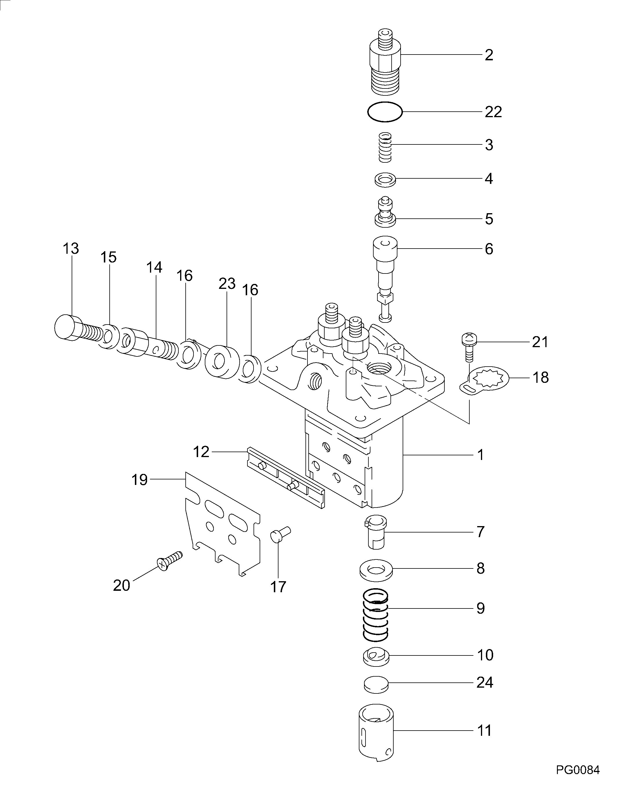
Fuel Injection Pump
Vehicle engine
INDUSTRIAL L3E
Engine
L3E
Serial start-end
0507-
Info
Injector Nozzle
093500-3840
Injector nozzle:
0935003840
Components :
Scheme #.#:
№
Qty
Part num
Name
Remarks
Manufacture num
000
[01]
09450-08460
PUMP ASSY, INJECTI
PFR3NC
-0610
Include in ##:
09450-08460
as PUMP ASSY, INJECTI
Cross reference number
Part num
Firm num
Firm
Name
09450-08460
PUMP ASSY, INJECTI

Information:
ROCKER ARM SHAFT ASSEMBLY
1. Fuel return line (one each head). 2. Bolts and locks (four each head).4. Remove rocker arm shaft assembly (3). Remove push rods (4).
REMOVING ROCKER ARM SHAFT ASSEMBLY
3. Rocker arm shaft assembly (one each head). 4. Push rods (eight each head).Install Rocker Arm Shaft Assemblies
1. Lubricate the cam followers, push rods, and rocker arm shaft assembly with clean engine oil (SAE 30).2. Install push rods. Position the rocker arm shaft assembly on the cylinder head.3. Install the rocker arm shaft assembly retaining bolts and locks. Tighten bolts to 18 5 lb. ft. (2.5 0.7 mkg) and bend the locks.4. Install the fuel return line.5. Adjust the intake valve clearance to .015 in. (0.38 mm) and the exhaust valve clearance to .025 in. (0.64 mm).6. Install valve cover. Install valve cover retaining bolts and tighten bolts to 120 24 lb. in. (138 28 cm.kg).Disassemble Rocker Arm Shaft Assembly
1. Remove retaining bolts and locks from each end of rocker arm shaft assembly and disassemble the rocker arm shaft assembly.
ROCKER ARM SHAFT ASSEMBLY DISASSEMBLED
1. Rocker arm shaft. 2. Rivet. 3. Washers (eight). 4. Rocker arms (two per cylinder). 5. Adjusting screw. 6. Bracket. 7. Oil supply hole.Assemble Rocker Arm Shaft Assembly
1. The oil holes in shaft (1), arms (4) and bracket (6) must be clean and free of dirt or foreign material.2. Install adjusting screws (5) into rocker arms (4) so they extend .44 in. (11.2 mm) below arm. This will avoid forcing valves into piston crowns when rocker arm assembly is installed on cylinder head.
ROCKER ARM SHAFT ASSEMBLY
1. Rocker arm shaft. 2. Rivet. 3. Washers (eight). 4. Rocker arms (two per cylinder). 5. Adjusting screw. 6. Bracket. 7. Oil supply hole.3. Install arms (4) on shaft with washers (3) positioned as shown.4. Position shaft (1) and arms (4) into bracket (6) so screws (5) are on the same side of bracket (6) as oil supply hole (7). Rivet (2) must be on top when shaft (1) is positioned into bracket (6). Later rocker arm shaft assemblies have machined flats (8). The machined flats must be on top when shaft (1) is positioned into bracket (6).
LATER ROCKER ARM SHAFT ASSEMBLY
1. Rocker arm shaft. 6. Bracket. 8. Machined flats (four per shaft).