Rating:
Information pump assy, injecti Denso
Product
Fuel Injection Pump
Vehicle engine
INDUSTRIAL S4L
Engine
S4L
Serial start-end
0406-
Info
Injector Nozzle
093500-3840
Injector nozzle:
0935003840
Components :
Scheme #.#:
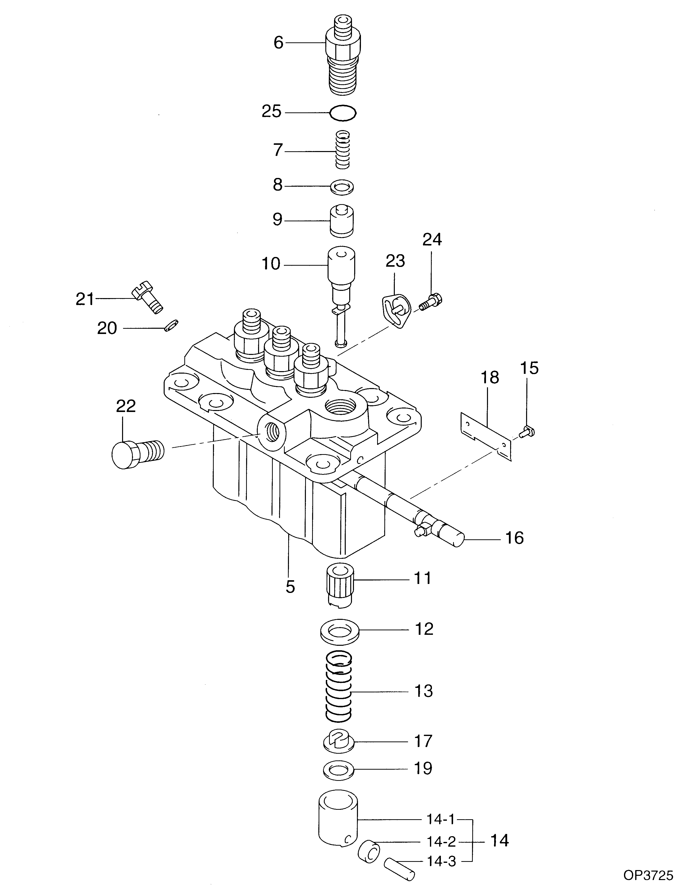
№
Qty
Part num
Name
Remarks
Manufacture num
000
[01]
09450-08370
PUMP ASSY, INJECTI
PFR4M
Include in ##:
09450-08370
as PUMP ASSY, INJECTI
Cross reference number
Part num
Firm num
Firm
Name
09450-08370
PUMP ASSY, INJECTI

Information:
The 1673C Engine is a 638 cu. in. (10,5 liters) displacement, 4-stroke cycle, six cylinder, turbocharged, diesel engine. The cylinder bore is 4.75 in. (120,6 mm) and the piston stroke is 6.00 in. (152,4 mm). The firing order is 1-5-3-6-2-4. The engine weighs approximately 1940 lbs. (880 kg) without coolant or oil.Inlet air filtered by a dry-type air cleaner, is compressed by a turbocharger before entering the engine cylinders. The turbocharger is driven by the engine exhaust.A plunger and barrel-type fuel injection pump meters and pumps filtered fuel to a precombustion chamber for each cylinder. The fuel is delivered to the precombustion chamber under high pressure. Injection for each cylinder begins at 13 degrees and 30 minutes before the piston reaches top center on the compression stroke.A hydraulic governor controls the fuel injection pump out-put to maintain a constant engine RPM under varying work loads. A speed limiting device, in the governor, limits engine speed until engine oil pressure builds up.The engine is of overhead valve design, having one inlet and one exhaust valve for each cylinder. The camshaft, geared and timed to the crankshaft, actuates rocker arms and valves through mechanical lifters and push rods. The timing gears are located on the front of the engine.The starting system is direct electric and uses a 24-volt starting motor. A 12-volt starting motor is optional.Coolant for the engine is used to cool the engine lubricating oil. A full-flow temperature regulator, in the cylinder head at the front of the engine, provides for quick engine warm-up, and allows free circulation of coolant after operating temperature has been reached.Lubrication for the engine is supplied by a gear-type pump. The pump provides full pressure lubrication to the engine internal and external parts.The lubricating oil is both cooled and filtered. Bypass valves in the oil cooler assembly provide unrestricted flow of lubricating oil to the engine parts when oil viscosity is high or, if either the oil cooler or the oil filter element should become clogged.Air Induction And Exhaust
Air induction and exhaust system parts include: 1-Exhaust manifold. 2-Inlet manifold. 3-Engine cylinder. 4-Air inlet. 5-Turbocharger compressor impeller. 6-Turbocharger turbine wheel. 7-Exhaust outlet.This engine has an exhaust driven turbocharger to provide compacted air to the cylinders.The exhaust gases enter the turbine housing and are directed through the blades of a turbine wheel, causing the turbine wheel and a compressor wheel to rotate.Filtered inlet air from the air cleaners is drawn through the air inlet of the compressor housing by the rotating compressor wheel. The air is forced to the inlet manifold of the engine and is compressed by action of the compressor wheel.When the engine load increases, more fuel is injected into the engine cylinders. The volume of exhaust gas increases, this causes the turbocharger turbine wheel and compressor impeller to rotate faster. The increased RPM of the impeller increases the quantity of inlet air. As the turbocharger provides additional inlet air, more fuel can be burned; hence more horsepower derived from the engine.The turbocharger
Air induction and exhaust system parts include: 1-Exhaust manifold. 2-Inlet manifold. 3-Engine cylinder. 4-Air inlet. 5-Turbocharger compressor impeller. 6-Turbocharger turbine wheel. 7-Exhaust outlet.This engine has an exhaust driven turbocharger to provide compacted air to the cylinders.The exhaust gases enter the turbine housing and are directed through the blades of a turbine wheel, causing the turbine wheel and a compressor wheel to rotate.Filtered inlet air from the air cleaners is drawn through the air inlet of the compressor housing by the rotating compressor wheel. The air is forced to the inlet manifold of the engine and is compressed by action of the compressor wheel.When the engine load increases, more fuel is injected into the engine cylinders. The volume of exhaust gas increases, this causes the turbocharger turbine wheel and compressor impeller to rotate faster. The increased RPM of the impeller increases the quantity of inlet air. As the turbocharger provides additional inlet air, more fuel can be burned; hence more horsepower derived from the engine.The turbocharger