Rating:
Information pump assy, injecti Denso
Product
Fuel Injection Pump
Vehicle engine
INDUSTRIAL S4L
Engine
S4L
Serial start-end
0406-
Info
Injector Nozzle
093500-3840
Injector nozzle:
0935003840
Components :
Scheme #.#:
№
Qty
Part num
Name
Remarks
Manufacture num
000
[01]
09450-08340
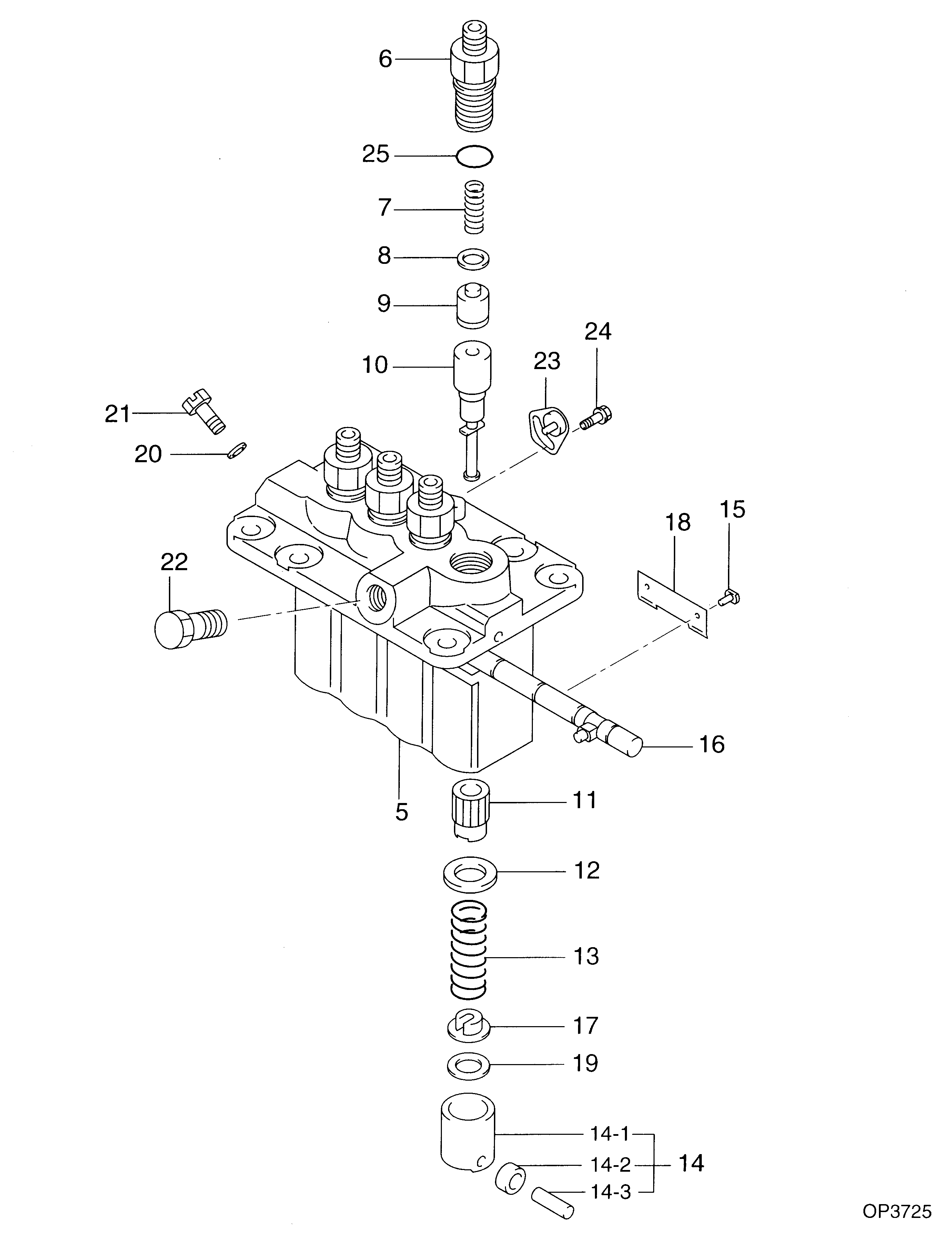
PUMP ASSY, INJECTI
PFR4M
Include in ##:
09450-08340
as PUMP ASSY, INJECTI
Cross reference number
Part num
Firm num
Firm
Name
09450-08340
PUMP ASSY, INJECTI

Information:
start by:a) remove flywheel (BrakeSaver) 1. Disconnect BrakeSaver lubrication oil line (1) from the fitting in the BrakeSaver housing. 2. Disconnect the oil line from fitting (5).3. Remove two short bolts (2) and two longer bolts (4) that hold manifold (3) to the BrakeSaver housing. Remove manifold (3) from the BrakeSaver control valve.4. Remove the O-ring seals from the manifold. The two longer bolts (4) from the manifold can be used as forcing screws to remove the BrakeSaver from the flywheel housing.5. Install a 3/8"-16 NC forged eyebolt in the top of the BrakeSaver housing and fasten a hoist. 6. Install tooling (A) on the BrakeSaver housing and rotor. Tooling (A) holds the BrakeSaver housing and rotor assembly together at removal. This prevents damage to the rotor rings and seals.7. Remove bolts (6) that hold BrakeSaver housing (7) to the flywheel housing.8. Use bolts (4) as forcing screws and tighten the bolts evenly to remove BrakeSaver housing (7) from the flywheel housing. The weight is 190 lb. (86 kg).Install Brakesaver
1. Install tooling (A) on BrakeSaver housing and rotor. Tooling (A) holds the BrakeSaver housing and rotor assembly together at installation. This prevents damage to the rotor rings and seals.2. Install a 3/8"-16 NC forged eyebolt in the top of the BrakeSaver housing and fasten a hoist.3. Install two 5/8"-18 guide pins (3) in the crankshaft as shown. Make sure dowel (2) is in alignment with the dowel hole in the rotor assembly and put BrakeSaver housing (1) in position in the flywheel housing.4. Install the three bolts that hold the BrakeSaver housing to the flywheel housing. Remove tooling (A) and guide pins (3). 5. Connect the oil line to fitting (6).6. Inspect the O-ring seals for damage and make replacements if needed. Install O-ring seals (4) and (5). Put clean oil on the O-ring seals.7. Install manifold (7) into the BrakeSaver control valve and install the four bolts that hold the manifold to the BrakeSaver housing. 8. Connect BrakeSaver lubrication oil line (8) to the fitting in the BrakeSaver housing.end by:a) install flywheel (BrakeSaver)Disassemble Brakesaver
start by:a) remove BrakeSaver1. Remove tooling (A) from the BrakeSaver housing and rotor. Tooling (A) prevents damage to the rotor seals and rings at removal of the BrakeSaver housing. 2. Remove bolts (1) from gear plate (2). Remove the plate. 3. Make identification as to the location of stator (3) with housing (4). Remove bolts (5) and the stator. 4. Turn the stator over and remove spiral ring (6). 5. Turn the stator over again. Remove sleeve assembly (9). Remove O-ring seal (7) and lip type seal (8) from the sleeve. 6. Remove O-ring seal (11) and the six smaller O-ring seals from the oil holes on the housing.7. Remove rotor assembly (12).8. Remove seal ring (10) from both sides of the rotor. 9. Remove carrier (13) and wear sleeve (14) with tooling (B) from both sides of the rotor. 10. Remove spiral ring (15). Turn the housing over and remove sleeve assembly (17).