Rating:
Information pump assy, injecti Denso
Product
Fuel Injection Pump
Vehicle engine
INDUSTRIAL E3100
Engine
E3100
Serial start-end
0305-
Info
Injector Nozzle
093500-5640
Injector nozzle:
0935005640
Components :
Scheme #.#:
№
Qty
Part num
Name
Remarks
Manufacture num
000
[01]
09450-08200
PUMP ASSY, INJECTI
-0609
Include in ##:
09450-08200
as PUMP ASSY, INJECTI
Cross reference number
Part num
Firm num
Firm
Name
09450-08200
PUMP ASSY, INJECTI

Information:
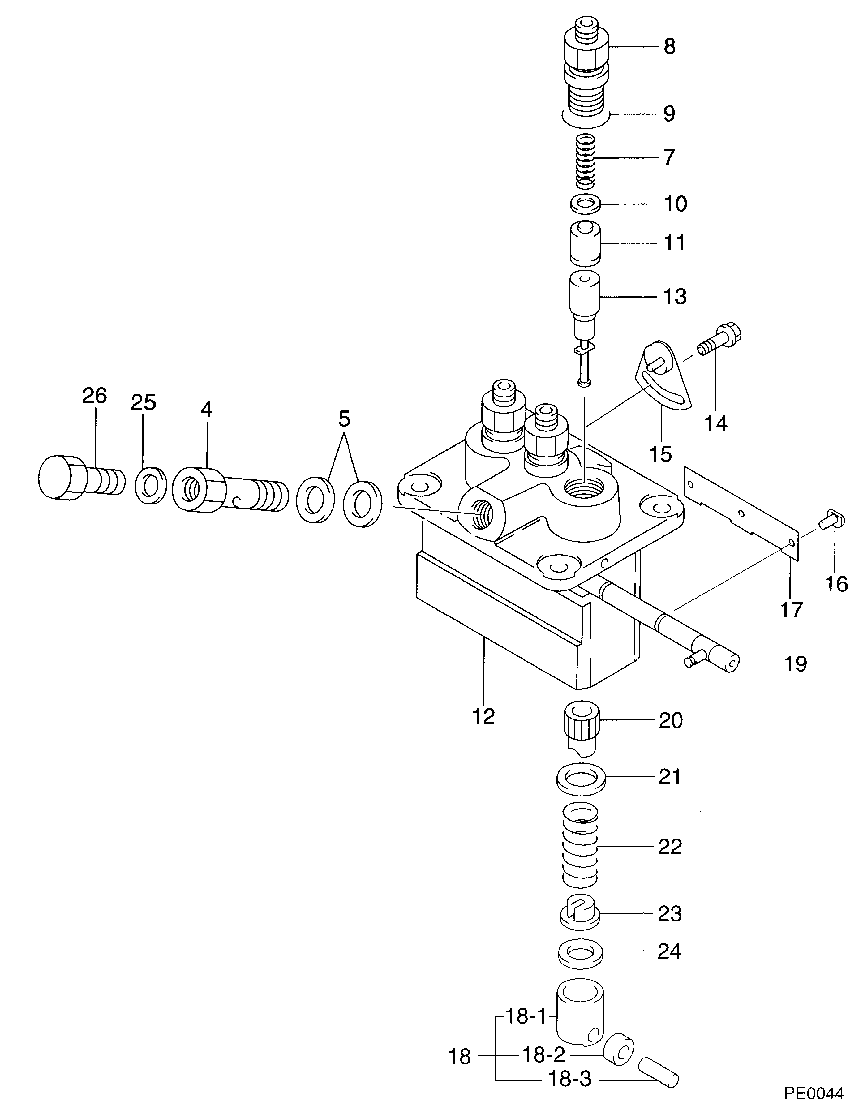
1. Remove plate (2) from the idle screw housing.2. Remove cover (1) for the idle screw. 3. Remove two bolts (7) and lock. Remove lever (6) for fuel shutoff solenoid.4. Remove idle screw (4). Remove bolt (3) and idle screw housing (5). 5. Remove screw (8) that holds rack stop collar (10) to the governor shaft.6. Remove rack stop collar (10) and spring.7. Remove bolts (9) that hold the governor housing to the fuel injection pump housing. Remove the governor housing. 8. Remove seat (18), wave washer (17), washer (16), wave washer (15) and governor spring (14).9. Remove washer (13).10. Remove three bolts (11) and locks that hold cylinder and weight assemblies (12) to the pump housing. Remove the cylinder and weight assemblies from the rack.Connection Of Governor To Fuel Injection Pump Housing
1. Put cylinder and weight assemblies (1) on the fuel injection pump housing. Be sure the groove (slot) in piston (2) is engaged in groove (slot) in rack (3). 2. Install the lock and three bolts (4) that hold the cylinder and weight assemblies on the pump housing. Make sure washer (8) is between wave washers (7) and (9).3. Install washer (6), governor spring (5), wave washer (7), washer (8), wave washer (9) and seat (10) on the cylinder and weight assemblies. 4. Install the spring and rack stop collar (13).5. Install the screw that holds the collar to the bolt.6. Install idle screw housing (11). Install idle screw (12).7. Install lever (14), lock and bolts for the fuel shutoff solenoid.8. Install the cover for the idle screw.9. Install the plate for the idle screw housing.end by:a) install fuel injection pump housing and governorb) make adjustments to the rack and governor (see RACK SETTING and GOVERNOR ADJUSTMENTS in TESTING AND ADJUSTING)
1. Put cylinder and weight assemblies (1) on the fuel injection pump housing. Be sure the groove (slot) in piston (2) is engaged in groove (slot) in rack (3). 2. Install the lock and three bolts (4) that hold the cylinder and weight assemblies on the pump housing. Make sure washer (8) is between wave washers (7) and (9).3. Install washer (6), governor spring (5), wave washer (7), washer (8), wave washer (9) and seat (10) on the cylinder and weight assemblies. 4. Install the spring and rack stop collar (13).5. Install the screw that holds the collar to the bolt.6. Install idle screw housing (11). Install idle screw (12).7. Install lever (14), lock and bolts for the fuel shutoff solenoid.8. Install the cover for the idle screw.9. Install the plate for the idle screw housing.end by:a) install fuel injection pump housing and governorb) make adjustments to the rack and governor (see RACK SETTING and GOVERNOR ADJUSTMENTS in TESTING AND ADJUSTING)