Rating:
Information pump assy, injecti Denso
Product
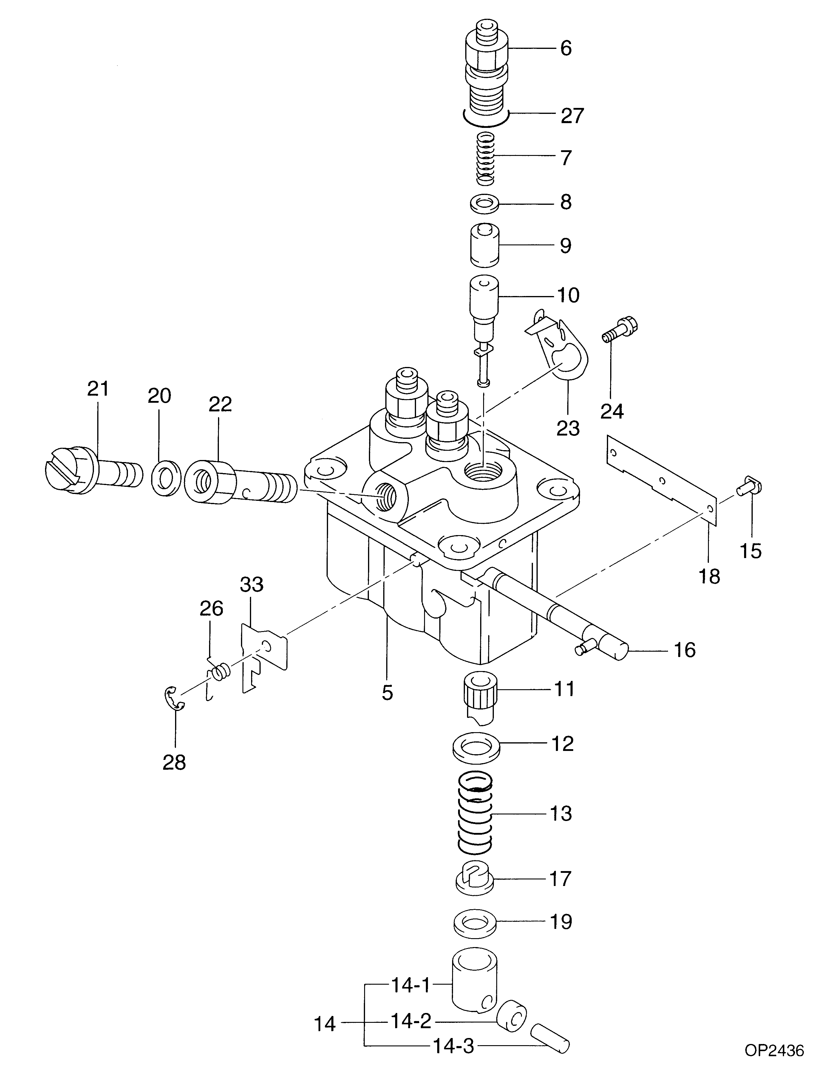
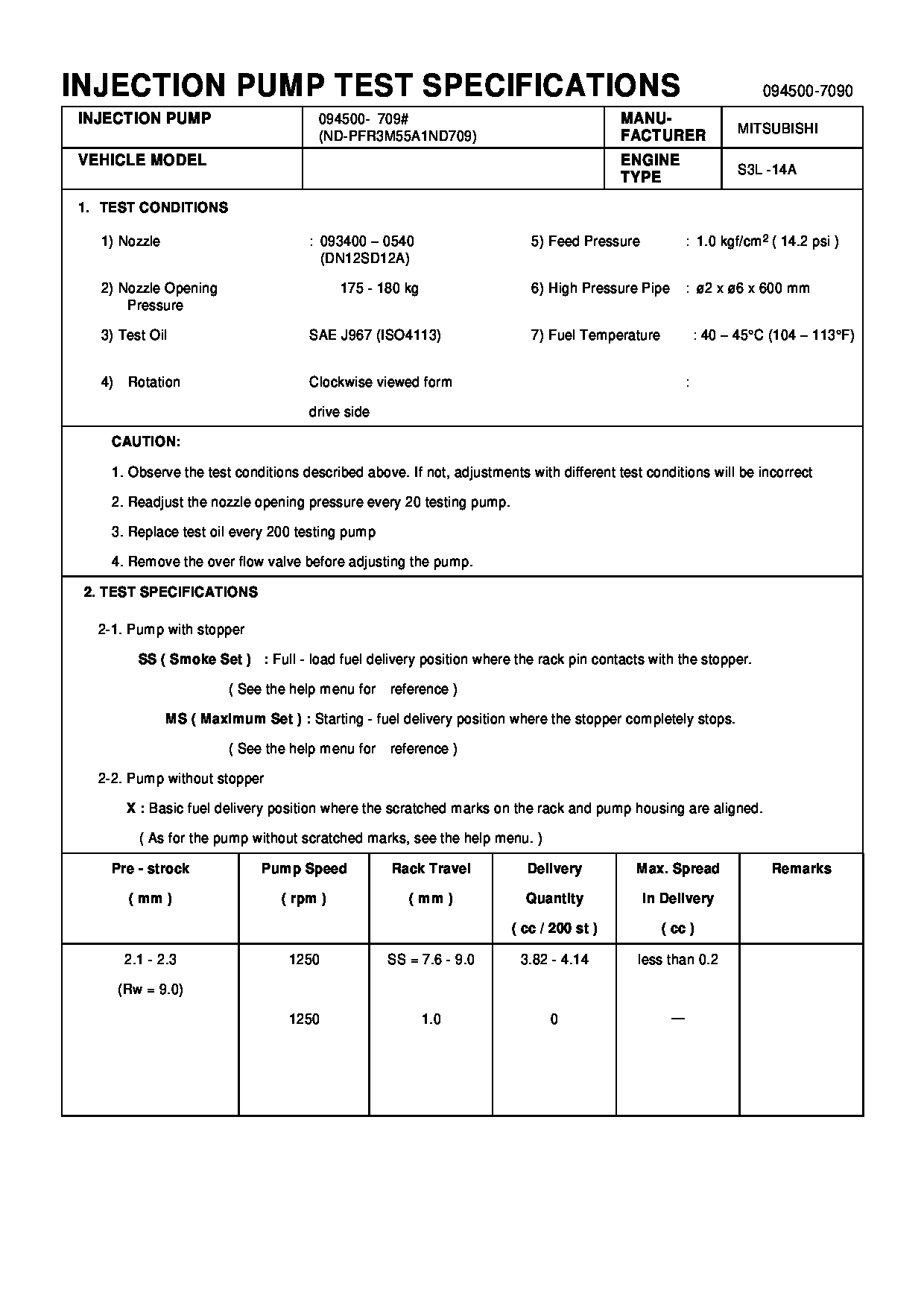
Fuel Injection Pump
Vehicle engine
agricultural machine S3L-14A
Engine
S3L-14A
Serial start-end
9705-
Info
Injector Nozzle
093500-3840
Injector nozzle:
0935003840
Components :
Scheme #.#:
№
Qty
Part num
Name
Remarks
Manufacture num
Cross reference number
Part num
Firm num
Firm
Name
09450-07090
PUMP ASSY, INJECTI

Information:
Input Modules
The following modules are input modules:
Thermocouple Module
RTD Input Module
Digital Modules
Analog ModulesWhen you apply a voltage to the channel, the relay is energized. An energized input will close all of the contacts that are normally open. An energized input will open all of the contacts that are normally closed. Digital modules are used to determine whether a circuit is ON/OFF. A number of modules are available. The MMS modules have sixteen channels. Discrete Output Modules
The programmable logic controller discrete output modules consist of analog modules and digital modules. Control of Voltage is provided by the output modules. A module provides power for the following list of functions: energizing the lamps, energizing the relays, energizing the fuel shutoff solenoid and energizing the air shutoff solenoid.Replacing a Module
Disconnect the power supply.
To avoid damage to electronic components, do not remove the processor from the SLC 5/04 Chassis until all power is removed from the power supply.Do not expose memory modules to surfaces or areas that may typically hold an electrostatic charge.
Press the retaining clips at the top of the module and press the retaining clips at the bottom of the module.
Remove the module from the chassis.
To avoid potential damage to the processor, handle all modules by the ends of the carrier or edges of the plastic housing. Skin oil or dirt can corrode metallic surfaces, inhibiting electrical contact.
Align the module and the guides in the chassis.
Gently slide the module in the chassis. Secure the top retainer clips and secure the bottom retainer clips.
Install a wire tie in order to secure the wiring.
Illustration 1 g00563310
Cover any unused slots. This protects the chassis.
Verify that the new module corrects the problem.