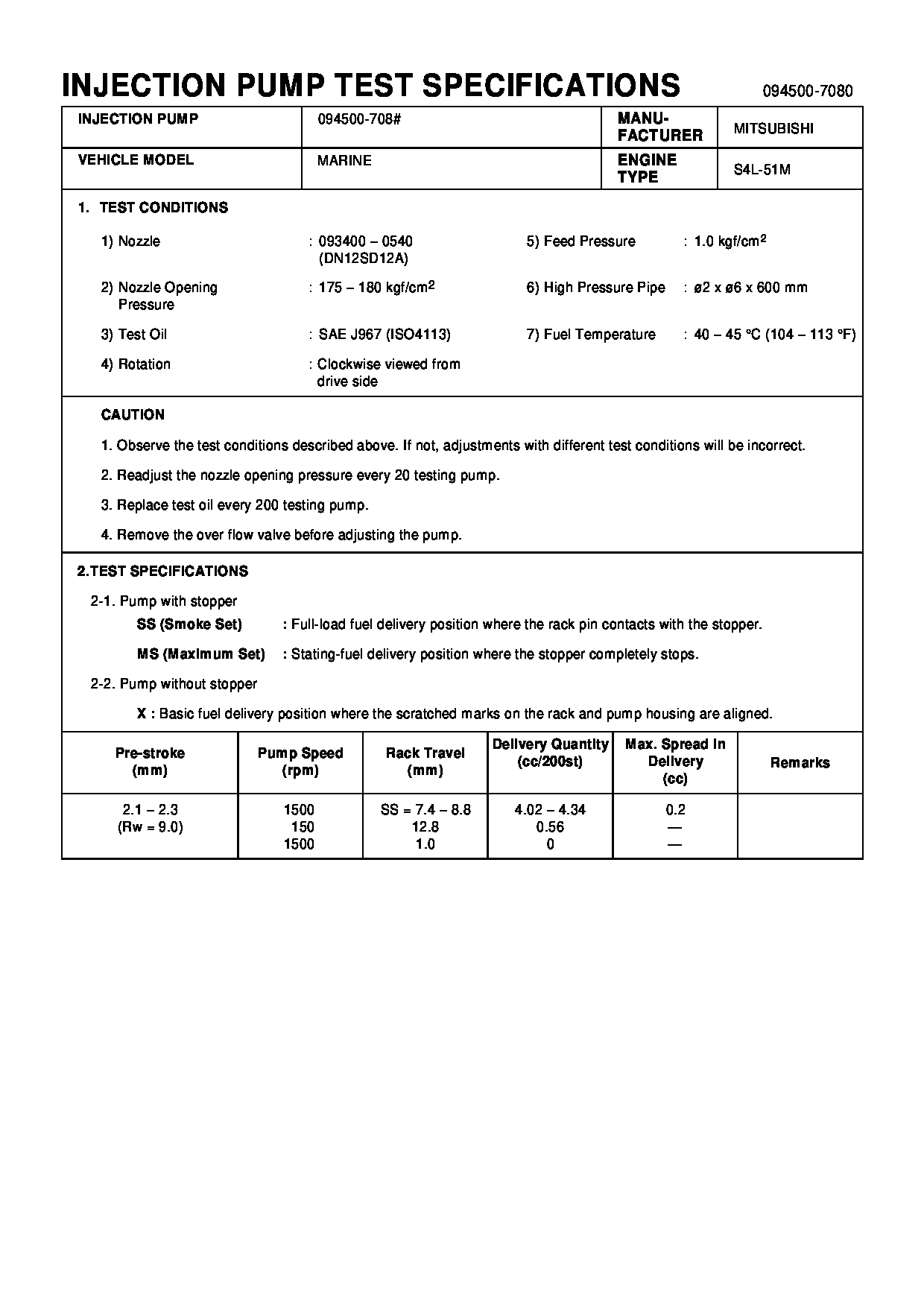
Rating:
Information pump assy, injecti Denso
Product
Fuel Injection Pump
Vehicle engine
MARINE S4L-51M
Engine
S4L-51M
Serial start-end
9705-
Info
Injector Nozzle
093500-3840
Injector nozzle:
0935003840
Components :
Scheme #.#:
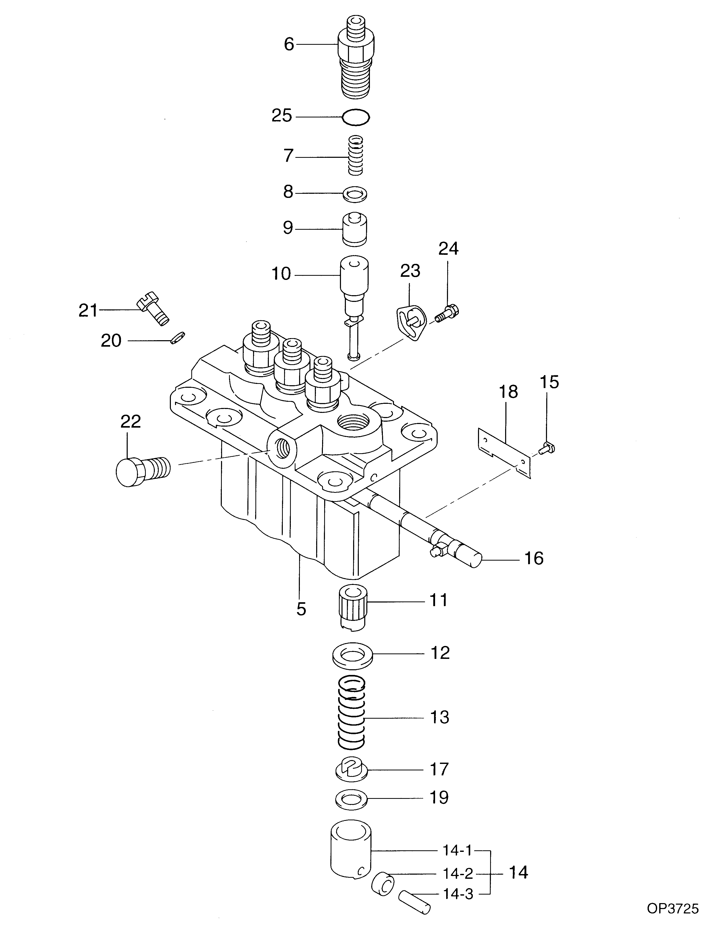
№
Qty
Part num
Name
Remarks
Manufacture num
000
[01]
09450-07080
PUMP ASSY, INJECTI
PFR4M
Include in ##:
09450-07080
as PUMP ASSY, INJECTI
Cross reference number
Part num
Firm num
Firm
Name
09450-07080
PUMP ASSY, INJECTI

Information:
start by:a) remove pistons 1. Remove bearings (3) from the connecting rod and connecting rod cap.2. Remove retainer ring (1) with tool (A).3. Remove pin (2) and connecting rod (4) from the piston. 4. Remove the piston rings (5) from the piston with tool (B). Clean the piston ring grooves on the pistons with an acceptable ring groove cleaning tool. See USE OF PISTON PIN BEARING REMOVAL AND INSTALLATION TOOLS, SPECIAL INSTRUCTIONS, Form No. SMHS7295.5. Heat the connecting rod (4) in an oven to a temperature of 350°-500°F (177°-260°C). Never use a direct flame to heat a connecting rod. 6. Put connecting rod (4) in position on the base plate of tooling (C). Put a new rod pin bearing (6) on the adapter part of tooling (C). The old bearing is pushed out by tooling (C) as the new bearing is installed.7. Use tooling (C) to push the new bearing into the connecting rod until the push adapter of tooling (C) makes full contact with the connecting rod surface.8. Use a pin boring machine to make the rod pin bearing the correct size. The bore in the new rod pin bearing must be 2.0012 .0003 in. (50.830 0.008 mm).9. Check the clearance between the ends of the piston rings. See PISTONS AND RINGS in SPECIFICATIONS.10. Install the oil ring spring in the oil ring groove of the piston. The oil ring is to be installed over the spring with the oil ring end gap 180° from the oil ring spring joint. 11. Install the oil ring on the piston with tool (B).12. Install the second (intermediate) piston ring with the side that has the identification "UP-2" toward the top of the piston with tool (B).13. Install the first (top) piston ring with the side that has the identification "UP-1" toward the top of the piston with tool (B). After the installation of all three piston rings, put the piston rings in position so the end gaps are 120° apart. 14. Put the piston in position on connecting rod (4). Put clean engine oil on pin (2) and install the pin. Install retainer rings (1) with tool (A). Make sure the retainer rings are in the grooves of the piston.15. Install bearings (3) in the connecting rod and connecting rod cap.end by:a) install pistons